Better comprehension of aerodynamics and development of superior materials during the late 20th century revived the utility of Wind Turbines for harnessing wind energy. Their traditional applications were water pumping and corn grinding [1].
Government policies in many parts of the world favour wind electricity as a means to cut greenhouse gas (GHG) discharges and water use by the power industry, diversify power generation sources for better price stability over the long term, and technological advancements to boost global competitiveness [2].
Discover our Turnkey Robotic Wind Energy Solutions
Cybernetik has delivered customized automation and equipment solutions for the wind energy industry with State-of-the-art flexible Robotic Machining Systems for Wind Turbine Blades.
About 28% of globally produced electricity came from renewables in 2020 [3]. Global Wind Energy Council (GWEC) placed wind power generation at 743 giga-watts (GW) at end-2020 [4], representing 6% of global power [5]. Onshore or land-based wind turbines contributed 707.4 GW of the 743 GW [5], the balance coming from offshore turbines based on water bodies.
China topped the list of generated wind power with 288.32 GW at end-2020 followed by the United States (122.32 GW), Germany (62.85 GW), India (38.63 GW), and Spain (27.24 GW) [6]. Denmark comes first with wind as the source for 41% of its electricity at end-2019. Next in line were Ireland (28%), Portugal (24%), Germany (21%), and Spain (19%) [7].
In many countries, wind power has achieved or exceeded grid parity wherein generation costs equal or are less than that from conventional sources [2]. This is welcome news for a world looking to cut carbon emissions to counter the menace of Global Warming and Climate Change.
What makes this critically significant is that the other two applications of energy viz. transport and heating are particularly tough to decarbonize. With renewable sources available, electricity is easier to de-carbonize. For example, renewables plus nuclear sources provide 36.7% of the world’s electricity but only 15.7% of the global energy [8].
The Industry Standard: Three Blade Horizontal Axis Wind Turbine (HAWT)
Efficiency and better controllability make the three-blade HAWT the industry standard. And with its global supply chain firmly entrenched, it will continue to be so for the near future. However, HWATs are hyper sensitive to alterations in blade design and profile [1].
Rotor speed is hard to control in vertical axis wind turbine (VAWT). This variant also suffers from low tip speed ratio. Improvements however can make the VAWT more useful in the future [1].
For more than one reason, three is the optimum number of blades for the HAWT [1]:
These are smoother than the faster but jerky one- and two- bladed HAWTs.
Slight improvement in efficiency for a four-bladed HAWT vis-à-vis its three-bladed version does not justify the escalated cost of manufacturing an extra blade. Besides, heavier four-bladed turbines impose greater load on the tower.
One- and two- bladed designs suffer from poor aesthetics and greater wear. Birds are more likely to crash into them.
Efficiency & Blade Geometry
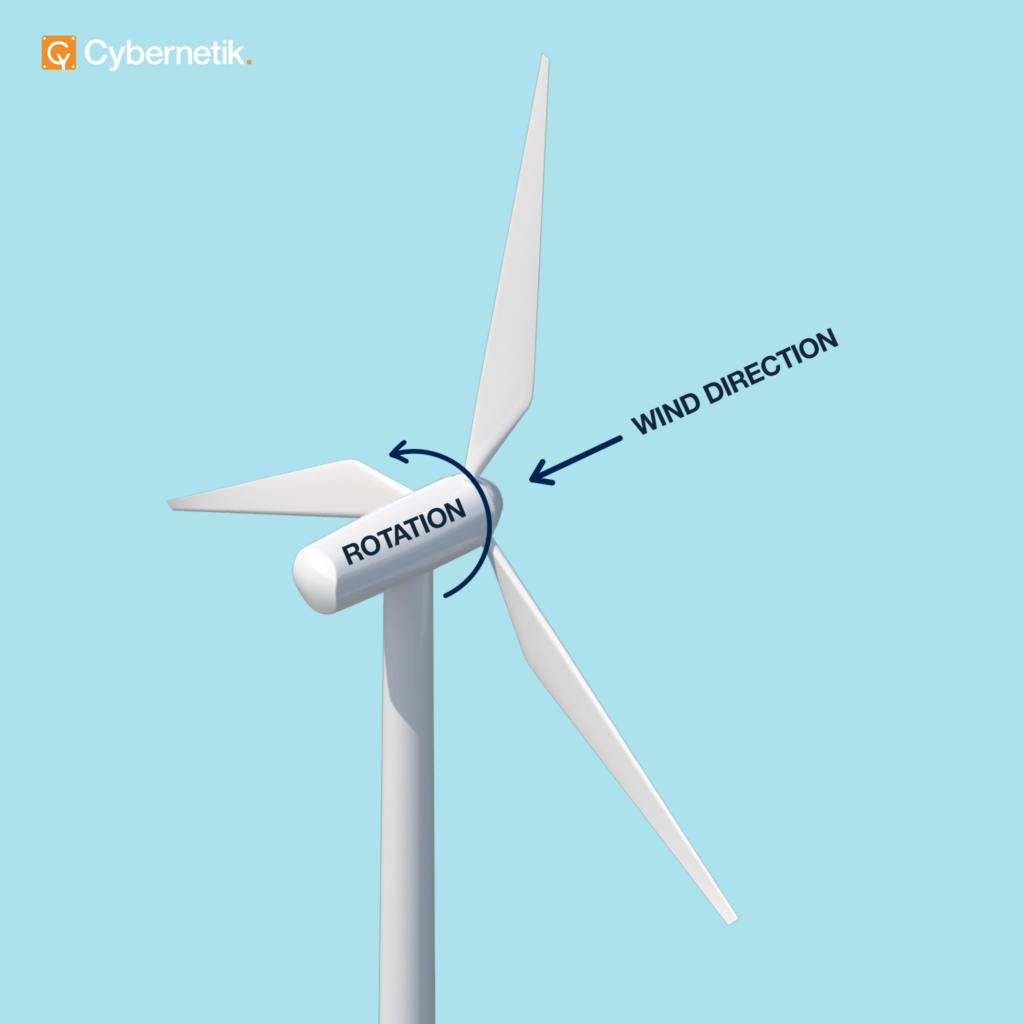
Horizontal axis wind turbine (HAWT) faces the wind. It is the relative wind i.e. wind incident on the turbine blade that produces the Lift and Drag forces. The resultant of these forces has a component Thrust that helps rotation and Reaction that opposes rotation [1].
Wind Turbine Orientation
Defining the theoretical maximum efficiency (59.3%) of wind turbines is the Bertz Limit or Power Coefficient CP equalling 16/27 or 0.593 [1]. Actual efficiency falls below this number due to:
Wake Impacts relate to wind farms with multiple turbines. The downstream flow of one turbine becomes the upstream for another and lower the latter’s efficiency. Real estate and cabling costs limit the space between turbines, whereby eliminating wake effects is unfeasible.
Therefore, wind turbines are spaced to the following dimensions to minimize this impact [9] [10]:
5-10 rotor diameters in the direction of prevailing wind; and
3-5 rotor diameters in the direction of cross wind.
Tip Issues such as leading edge erosion disturb aerodynamics to lower efficiency as well as useful life [11].
Simplified Blade Geometries such as reducing angle of twist lower the manufacturing costs as also the efficiency. Twist is the angle between the chord line of the blade section at the root and that at the tip [13].
Losses in Drive Train viz. generator and gearbox are inevitable for parts that possess mass and move.
Methods to boost efficiency include:
High Lift to Drag Ratio Blade Shapes: Lift is the force that largely aids blade rotation. Drag majorly acts against blade rotation. Designers choose a ratio greater than 30 [1].
Optimized blade geometry consists of multiple aerofoil sections that are thicker and wider near the hub where they protrude into the wind. Those near the tip are thinner, narrower, and almost perpendicular to wind direction [1].
Sufficient Tip Speed Ratios: This ratio is the linear speed of the blade tip divided by the relative wind velocity. Optimized tip ratio for three blade HAWTs is 6-9 and that for its two blade version is 9-10 [1].
When tip speed ratio rises [1]:
Efficiency increases.
Noise, aerodynamic force, and centrifugal stress escalate.
Self-starting becomes more challenging.
Narrower blade profiles can be used to cut material and production costs. Such blades cannot withstand large forces though.
Appropriate Tip Shapes wherein the tip is located on the pitch axis delivers superior torque to thrust ratio. This design is widely used [13].
Serrated trailing edges near the tip are based on owl wings. These improve aerodynamic efficiency and lower noise by enabling smoother mixing of the flows on two sides of the aerofoil section [14]. Whalepower Corporation has developed blades with leading edge serrations that boost lift and reduce noise [15].
Following are the factors, some of which involve trade-offs, that determine the cross sectional geometry of the blade [1]:
Thicker sections withstand higher loads versus thinner ones that deliver higher tip ratios, lower drag, and lesser material and production costs. Advanced materials with greater strength will enable use of thinner sections.
Increasing angle of twist to improve lift vis-à-vis lowering it to simplify blade design and production which cuts design and manufacturing costs.
Vulnerability of blades to soiling and fouling as dust and insects accumulate on blade surface to disturb the aerodynamics and reduce efficiency.
Stall is the decline in lift and increase in drag at high angles of attack. It can be utilized beneficially to reduce lift for smaller turbines during high winds provided it is brought about gradually. Angle of attack is between chord line of blade cross section and the relative wind velocity vector.
Feathering is the reduction of angle of attack. The technique is generally used to reduce lift in high winds.
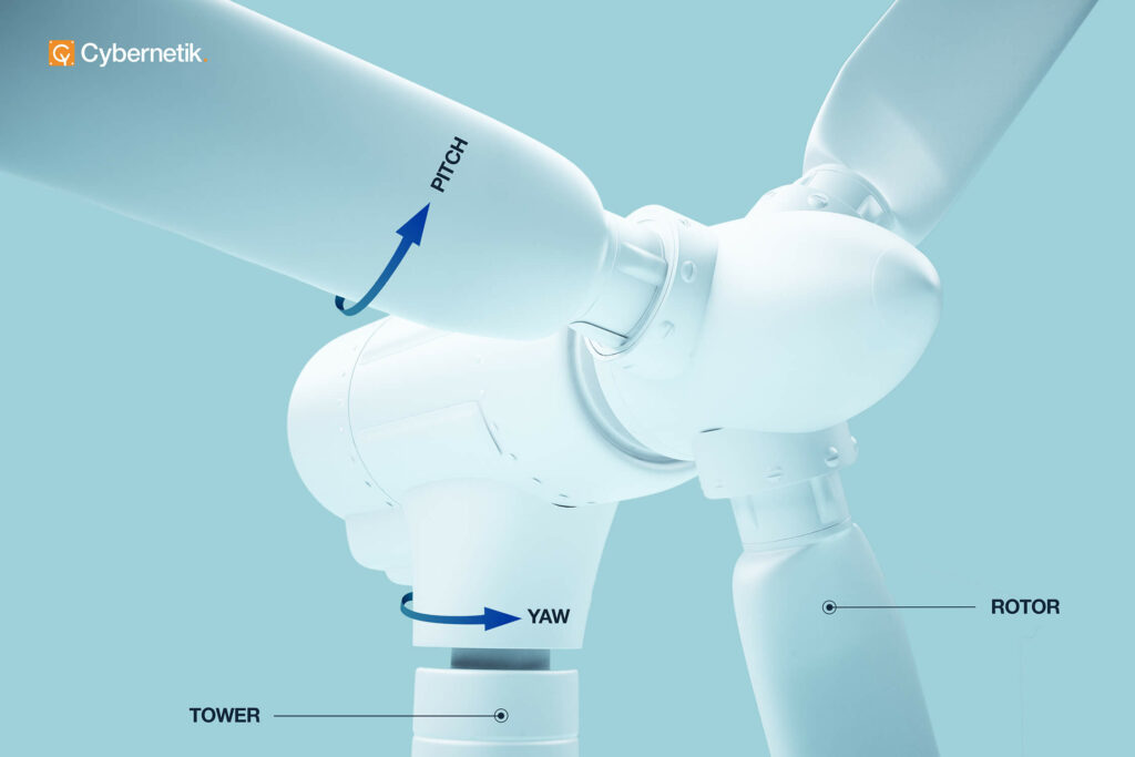
Pitch & Yaw
Pitching is the deliberate changing of angles of attack by twisting the blades along their length. This lowers or boosts lift respectively during high and low wind conditions [1]. Pitch drive is located in the hub. Rotation plane and chord line are separated by the pitch angle [12]. Yaw drive rotates the hub along the vertical axis to keep it facing the wind.
Loads & Design Considerations
Primary conditions factored in when understanding loads on blades are:
Extreme Operational Loading due to ultra-high wind speeds; non-standard operations such as starting, yawing, or shutdown; or occasional wind gusts during low winds [16].
Emergency Stops are effected by means of aerodynamic and mechanical brakes. The former involves turning either the blades or their tips through 900. Mechanical brakes are a back-up arrangement for the aerodynamic ones [17].
Parked 50-year Storm Scenario wherein the turbine is non-operational with a parked (locked) rotor and feathered blades [18].
Under these conditions, following loads are important [1]:
Aerodynamic Loads include lift and drag. These depend on the wind and blade velocities, angle of attack, surface finish, and yaw.
Centrifugal Loads caused by blade mass and their rotational speed are directed radially outward.
Gravitational Loads result from the blade mass acting downward.
Centrifugal and gravitational loads are crucial for turbines of or above 70 m diameter, slight for rotors up to 20 m, and insignificant for rotors of 10 m or below [1]. Blades that can resist these three loads can endure the following two minor loads [1]:
Gyroscopic Loads that yawing creates.
Operational Loads that yawing, pitching, generator connections, and braking produce.
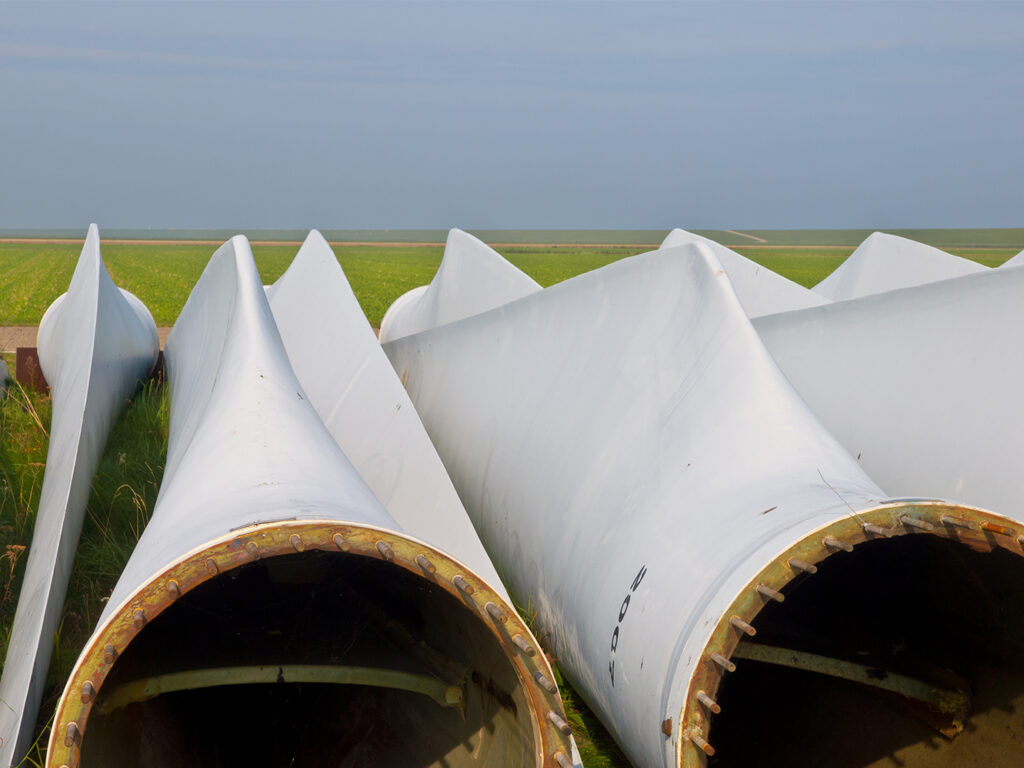
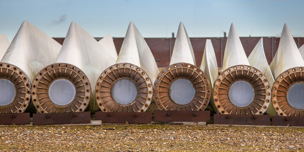
Root End Machining of Wind Turbine Blades
Fastening the blades to the hub is a skilled operation that requires precise machining to maintain the structural integrity of the turbine in view of the colossal loads we have noted earlier. Besides, this fastening has to be such that it does not interfere with pitching that has a direct impact on turbine efficiency.
Diameters of the turbine blades at the root end, where it attaches to the hub, are considerable – of 3 meters or more. The intersecting surfaces are sawn off and / or milled followed by removal of the sawn off ring. For accurate and robust fastening, both axial and radial bolts are inserted into purpose drilled slots. This complicates the operation.
Customized automation can handle the involved challenges via:
Automatic tool changer to deal with the multiple and sequential operations.
Employing precision equipment to accurately handle large parts.
Automated extraction of the sawn off ring, inspection of sawn surface, and marking of drill locations through exact centre and PCD (pitch circle diameter) calculations.
Wet and dry machining options for relevant requirements.
SCADA for data track and trace.
Dust collection system to maintain hygiene.
Finally
Wind generates the most renewable electricity globally after hydroelectricity [5]. The world added 93 GW in 2020 making it the best year for the worldwide wind industry, marking a 53% rise year-on-year. This will still be inadequate to reach net zero emissions by 2050 [4]. More wind turbines with superior designs is one way to reach the target.
Cybernetik is a 30+ year old Indian automation company that has successfully designed a number of bespoke systems.
Among these is a Root-End Machining for Wind Turbine Blades we designed for an industry leader. The system replaces traditional special purpose machinery (SPM) with robotic automation to seamlessly handle variations in blade diameter, reduce cycle time by 50%, eliminate rework, and improve accuracy.
Write to us at [email protected] to know how we can add value to your manufacturing plant.
References
Peter Schubel et al. Energies. “Wind Turbine Blade Design.” 2012.
Clean Energies Solutions Centre. “Policies to Support Wind Power Deployment.”
International Energy Agency (IEA). “Global Energy Review 2020.” 2020.
Global Wind Energy Council. “Global Wind Report 2021.”.
Centre for Climate and Energy Solutions. “Renewable Energy.”
NS Energy. “Profiling the Top Five Countries with the Highest Wind Energy Capacity.” 30 March, 2021.
World Population Review. “Wind Power by Country 2022.”
Hannah Ritchie et al. Our World in Data. “Electricity Mix.” 2020.
Philip McKay et al. Intech Open. “Turbine Wake Dynamics.” 2012.
Wind Farm Design. “Park Effect.”
Weather Guard Lightning Tech. “Leading Edge Erosion: A Big Problem for Wind Turbine Operators.” 17 January, 2021.
Mecaflux Heliciel. “Twisting blade Propeller and Profile Pitch.”
E. Ferrer et al. Journal of Physics: Conference Series. “Wind Turbine Blade Tip Comparison using CFD.” 2007.
Weather Guard Lightning Tech. “Does a Serrated Trailing Edge Cause Lightning Damage to Wind Turbine Blades?” 3 September, 2020.
Mike McLeod. Design Engineering. “Whale of an Idea.” 1 November, 2010.
Peter Madsen et al. National Renewable Energy Laboratory. “Predicting Ultimate Loads for Wind Turbine Design.” 1998.
Danish Wind Industry Association. “Wind Turbine Safety.” 30 July, 2003.
V. Valamanesh et al. Structural Safety. “Multivariate Analysis of Extreme Metocean Conditions for Offshore Wind Turbines.” July 2015.