
Key takeaways
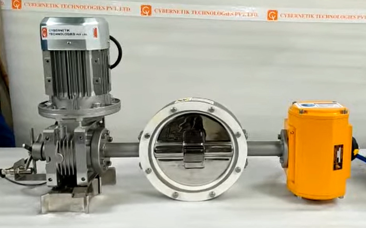
A motorized butterfly valve is two purchases in one, and buyers usually specify the first carefully and the second by default. The valve is chosen against pressure, temperature and media. The actuator is frequently chosen because it fits the mounting flange and the price is acceptable.
That is backwards. Most motorized butterfly valve failures in service are actuator failures rather than valve failures, and almost all of them trace to two decisions: torque sizing and duty cycle.
This guide covers the valve constructions and what each can seal against, why the actuator specification matters more than it appears, and how the selection differs in powder handling from fluid service.
Butterfly Valve Construction
Butterfly valves are not one design. The relationship between the stem, the disc and the seat determines what the valve can seal against and how long it lasts.
| Construction | How it seals | Suits | Limitation |
|---|---|---|---|
| Concentric, resilient seated | The disc presses into an elastomer liner that lines the bore | General service, powder isolation, water and air at moderate pressure | The liner is the wear part, and the disc rubs across it on every cycle |
| Double offset | The stem is offset so the disc cams away from the seat as it opens | Higher pressures and temperatures than resilient seating allows | Some seat contact remains, so wear continues, though far less |
| Triple offset | A third, conical offset gives torque seating with no rubbing | High temperature, high pressure and tight shut-off requirements | Considerably more expensive and usually more valve than a powder line needs |
| Demountable sanitary | Split housing allows blade, seat and seals to be removed for cleaning | Food and pharmaceutical duty with frequent product changeover | Not a pressure-rated design; built for hygiene rather than for duty severity |
For most process plants the choice is between the first and the last. Concentric resilient-seated valves are the workhorse, cheap and effective, with the liner as a known consumable. Demountable sanitary designs trade pressure capability for the ability to strip and clean the valve between products, which in a multi-product food or pharmaceutical plant is usually the deciding factor.
Double and triple offset designs solve problems that arise at pressures and temperatures well above typical powder and food processing duty. Specifying one where a resilient seat would serve is expensive capability that will not be used.
Why Motorize
Three reasons, and they justify different levels of actuator.
That last distinction matters commercially, because modulating duty and on-off duty need different actuators, and paying for one where the other is required is the most expensive way to get this wrong.
On-Off or Modulating: The Duty Cycle Trap
This is the single most common failure in motorized valve specification, and it is entirely avoidable.
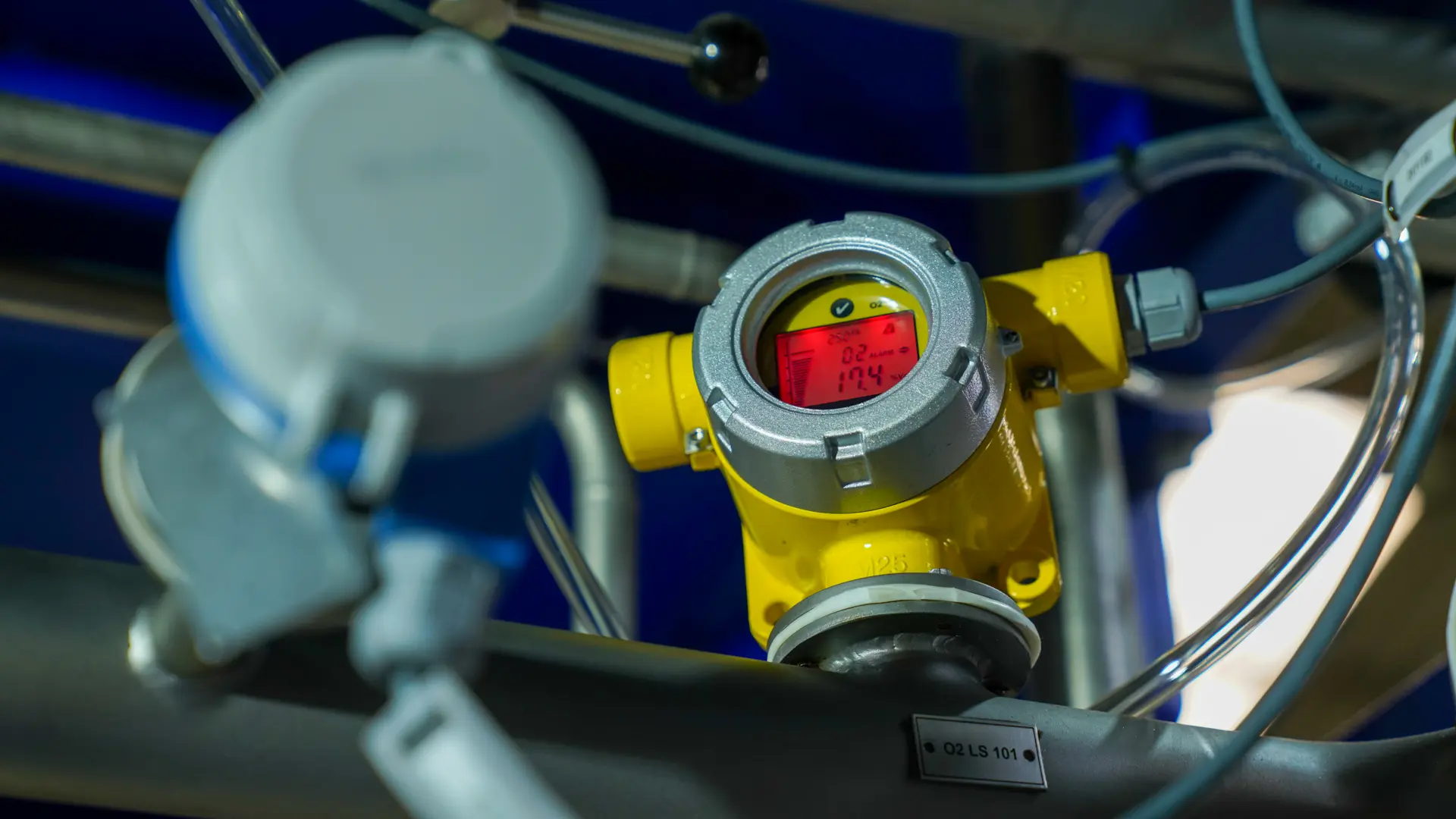
An electric actuator contains a motor, and motors heat when they run. Actuators are therefore rated for a duty cycle, expressed as the percentage of time they can operate within a period, along with a permitted number of starts per hour. An on-off actuator might be rated for a modest duty cycle and a few hundred starts an hour, which is ample for a valve that opens at the start of a transfer and closes at the end.
A modulating valve behaves completely differently. Under closed-loop control it makes small corrections continuously, which can mean thousands of starts an hour and near-continuous motor operation. An on-off actuator asked to do that overheats, and repeated thermal cycling destroys it. The valve is fine; the actuator fails within months and the plant concludes the equipment was poor quality.
The remedy is simply to state the duty honestly at inquiry. If the valve will hold intermediate positions under automatic control, specify a modulating-rated actuator with a high duty cycle and a starts-per-hour figure that matches the control loop. If it opens and closes on command, an on-off actuator is correct and considerably cheaper.
Sizing the Actuator: Torque
The second common failure. Actuator sizing is a torque calculation, and the torque a butterfly valve requires is not a single number.
Two factors then raise these figures. Differential pressure across the disc increases torque substantially, so a valve sized on normal operating pressure will stall at the maximum pressure the system can develop, which is usually the moment it most needs to close. And media matters: abrasive powder packing around the disc and seat raises break torque well above the clean condition.
Standard practice is to apply a safety factor to the calculated requirement, commonly in the range of one and a quarter to one and a half times, and to size against maximum differential pressure rather than nominal. An actuator sized exactly to the calculated torque has no margin for a seat that has stiffened, a disc that has packed or a supply voltage that is low.
Fail Position with an Electric Actuator
This differs from pneumatic actuation in a way that has real safety consequences.
A pneumatic actuator with a spring return has an inherent fail position: remove the air and the spring drives the valve to its safe state. An electric actuator has no such mechanism. On loss of power, the default behavior is to stop where it is, which may be fully open, fully closed, or anywhere between.
Where fail-in-place is the correct outcome, that is convenient and requires nothing. Where it is not, a fail-safe electric actuator is needed, achieving the safe position through a mechanical spring, a capacitor bank or a battery back-up. These cost more and they should be specified deliberately rather than discovered after a power interruption leaves a valve open on a silo.
The decision belongs with the process hazard assessment. A valve isolating two vessels, a valve on a dust collection line and a valve feeding a mill may each need a different answer, and none of them should be determined by what the standard actuator happens to do.
Feedback, Control and Integration
An actuator that has been commanded to close is not the same as a valve that is closed, and the difference matters whenever the sequence downstream depends on it.
 “Actuator torque must be sized for the maximum operating condition, because differential pressure, powder packing, and seat resistance can increase the torque required beyond normal operation.”

See it in action
Electric or Pneumatic
| Electric actuator | Pneumatic actuator | Comment | |
|---|---|---|---|
| Speed | Slower, typically seconds | Fast, often under a second | Pneumatic wins where cycle time matters |
| Fail behavior | Holds position unless spring or backup is specified | Spring return gives fail-safe inherently | This is the decision most often got wrong |
| Services required | Electrical supply only | Clean dry compressed air plus electrical for the solenoid | Electric wins where there is no air system |
| Modulating control | Precise positioning with feedback | Needs a positioner to modulate accurately | Electric is generally simpler for throttling duty |
| Duty cycle | Limited by motor heating; must be rated for the application | Effectively unlimited cycling | The most common electric actuator failure |
| Cost | Higher per unit | Lower per unit, plus the cost of the air system | Air system cost is often omitted from the comparison |
The row that decides most installations is services. A plant with an existing clean dry compressed air system will usually find pneumatic actuation cheaper and faster, with fail-safe behavior built in. A plant without one, or with a valve located far from the air network, will find that running air to a single valve costs more than motorizing it.
Butterfly Valves in Powder Handling
The application differs enough from fluid service to warrant its own treatment, and it is where most butterfly valves in a process plant actually sit.
In bulk solids handling, butterfly valves are predominantly isolation devices. They close the inlets and outlets of silos, hoppers, bins and containers, allowing a vessel to be sealed for maintenance, changeover or transfer. Wafer-style bodies are the norm, and the seat is the wear component that determines service life.
What they are generally not is flow controllers. Partially closing a butterfly valve on a cohesive powder encourages material to arch across the restricted opening and stop, and the disc itself becomes a shelf for material to build on. Where a controlled discharge rate is genuinely required, a rotary or metering valve does the job properly.
That distinction, throttling for fluids against metering for solids, is set out in the guide to flow control valves, and the wider valve taxonomy in the article on industrial valves.
One further variant is worth knowing. Split butterfly valves, where an active half on the receiving equipment mates with a passive half on the container, allow powder to transfer between vessels without exposing product or operator. In pharmaceutical handling of potent compounds this is the standard approach to contained transfer, and it is a butterfly valve doing a job no other valve geometry does as neatly.
Applications
Selection Checklist
- State the duty as on-off or modulating, and match the actuator duty cycle and starts-per-hour rating to it.
- Size torque against maximum differential pressure, not normal operating pressure, with a safety factor applied.
- Decide fail position from the process hazard assessment, and specify fail-safe hardware if fail-in-place is not acceptable.
- Select seat material against the product, temperature and cleaning chemistry, since the seat is the wear part.
- Confirm cleaning requirements, and choose a demountable design where frequent changeover applies.
- Specify position feedback appropriate to the sequence the valve participates in.
- Confirm enclosure rating and area classification, particularly where combustible dust is present.
- Include a manual override where commissioning or power failure would otherwise leave the valve unoperable.
Valves from Cybernetik
Cybernetik builds powder handling valves as part of complete process lines, engineered around the material rather than supplied as standalone components. Where the requirement is controlled discharge rather than isolation, the CT valve meters from 1,000 to 6,000 kg/hr with variable frequency drive control, zero leakage and vacuum compatibility, in SS304 or SS316 with a multi-blade or butterfly rotor.
Where a batch must be filled quickly and landed accurately, the combo valve provides separate coarse and fine feeding from one unit at the same capacity range, with independent actuators for each stage. Both are available with explosion resistant ATEX construction and hygienic GMP build, and both can be supplied with electric, pneumatic or electro-pneumatic actuation depending on whether the duty calls for modulating control or fast sequencing.
Cybernetik has operated for more than three decades, is headquartered in Pune with additional facilities in Gujarat and Raigad and international offices in the United States and UAE, and has installed over 6,000 systems across 30 plus countries, including more than 400 custom automation solutions. Further background is on the Cybernetik about page.