
Key takeaways
Wind turbine manufacturing is an unusual industry. It produces some of the largest moving structures ever built in series, to tolerances borrowed from machine tools, in factories where a significant share of the work is still done by hand. A single modern blade can exceed 100 metres and weigh over 50 tonnes, and the bolted joint holding it to the hub is machined to within a millimetre.
That combination of scale and precision is what makes the sector difficult and what makes it interesting. This article walks through how the major components are manufactured, sets out the constraints the industry is genuinely wrestling with rather than the ones that make good conference slides, and looks at where the practical opportunities sit over the next decade.
What Actually Gets Manufactured
A utility scale turbine breaks into four manufacturing programs that share almost nothing in process terms: rotor blades in composite, the nacelle and drivetrain in heavy mechanical assembly, the tower in rolled and welded steel, and the hub and structural castings in foundry and machining work. The design logic connecting them is covered in the article on axial flow turbine design. What follows is how each is built.
Blade Manufacturing
Blades are the hardest component to make and the one that most constrains how large turbines can grow. The process runs roughly as follows.
Mould preparation and layup
Blades are built in two halves, pressure side and suction side, in heated female moulds. Glass fibre fabrics, and carbon fibre in the spar caps of larger blades, are laid into the mould along with balsa or foam core materials. Layup remains substantially manual because ply geometry changes continuously along the span and the material has to conform to compound curvature. This is the single largest labour input in the whole turbine.
Resin infusion and cure
The mould is sealed under vacuum bagging and resin, usually epoxy, is drawn through the dry fabric stack. Infusion has to wet out every fibre before the resin begins to gel, across a part tens of metres long. Dry spots and voids created here become structural defects that no later stage can correct. The part is then cured under controlled heat.
Bonding and closing
Shear webs are positioned, adhesive is applied along the bond lines, and the two shells are closed together. Bond line thickness and adhesive coverage are critical and largely invisible once the mould shuts, which is why bond line quality is one of the most scrutinised characteristics in blade inspection.
Root end machining
The cured blade is demoulded and the root is cut to length, face milled, and drilled for the bolt ring that attaches it to the hub. Hole positions are held to within a millimetre on a pitch circle several metres across, on a composite section that is often more than 100 mm thick. The eight stage sequence and the tolerances involved are set out in the guide to wind turbine blade root machining.
Finishing, balancing and testing
Surfaces are ground, filled and coated for erosion and UV resistance, leading edge protection is applied, and the blade is weighed and balanced. Blades destined for a single rotor are matched by mass and moment so the assembled rotor runs without imbalance. Sample blades from each design undergo static and fatigue testing to certification standards.
Nacelle and Drivetrain Assembly
Nacelle production is heavy mechanical assembly rather than fabrication. A cast or welded bedplate receives the main shaft and main bearings, then the gearbox or direct drive generator, the converter, control cabinets, cooling systems, yaw drives and the nacelle cover.
Most of the value here is bought in. Gearboxes, bearings, generators and converters come from specialist suppliers, and the turbine manufacturer integrates and tests them. Assembled nacelles are run on test stands before shipping, because correcting a drivetrain fault at hub height, particularly offshore, costs orders of magnitude more than catching it in the factory.
Tower and Casting Manufacture
Steel towers are made from plate rolled into cylindrical cans, joined by longitudinal and circumferential submerged arc welds, with flanges welded at each end. Sections are blasted and coated, fitted with internal platforms, ladders and cabling, then shipped as the largest pieces that road or sea transport will accept. Weld quality governs fatigue life, so non destructive testing coverage is high.
Hubs, main frames and bearing housings are cast in ductile iron, then machined on large boring mills to hold bearing seats and blade flange interfaces within tolerance. These are unglamorous parts with long lead times that frequently sit on the critical path.
The Challenges the Industry Is Actually Facing
Manufacturing constraints, not turbine physics, set the pace at which wind scales. Seven recur across every serious discussion of the sector.
| Challenge | Why it persists | Where the opportunity sits |
|---|---|---|
| Manual composite layup | Blade geometry varies along the span and plies must conform to compound curves that resist automation | Automated fibre placement, robotic ply handling and machine vision inspection of layup before infusion |
| Precision at extreme scale | Tolerances stay in fractions of a millimetre while parts grow past 100 metres | Robotic machining referenced to the as moulded part rather than to drawing coordinates |
| Transport and logistics | Blades and tower sections exceed road and rail envelopes in most geographies | Segmented and modular blade designs, and near site manufacturing close to project locations |
| Skilled labour availability | Layup, bonding and finishing depend on experienced operators who take years to train | Automating the physically punishing and repetitive stages so skilled staff move to process control |
| Composite waste and end of life | Thermoset epoxy cannot be melted and reprocessed, so retired blades are hard to recycle | Thermoplastic and chemically recyclable resin systems, plus recovery of fibre from decommissioned blades |
| Supply chain concentration | Permanent magnets for direct drive generators depend on a narrow rare earth supply base | Magnet free and reduced magnet generator topologies, and regional supply chain build out |
| Cost per megawatt pressure | Auction driven procurement compresses margins across the whole supply chain | Yield improvement and rework elimination, where the recoverable cost actually sits |
The last row deserves emphasis because it is the one most often overlooked. In an auction driven market where selling price is fixed externally, margin comes from yield rather than from pricing. A rework rate reduced by a few percentage points on a component worth six figures is a larger commercial win than most procurement negotiations, and it compounds every shift.
Future Opportunities
 “As wind turbines grow larger, manufacturing becomes harder rather than easier, with tighter relative tolerances, higher scrap value, more complex handling, and greater consequences for every defect.”

See it in action
Where Automation Changes the Economics
The recurring theme across all of this is that wind manufacturing gets harder as it scales, not easier. Larger parts mean tighter relative tolerances, higher scrap value, more difficult handling and greater consequence for every defect. Manual processes that worked acceptably at 40 metres become the limiting factor at 100. That is precisely where robotic machining automation for wind components earns its place.
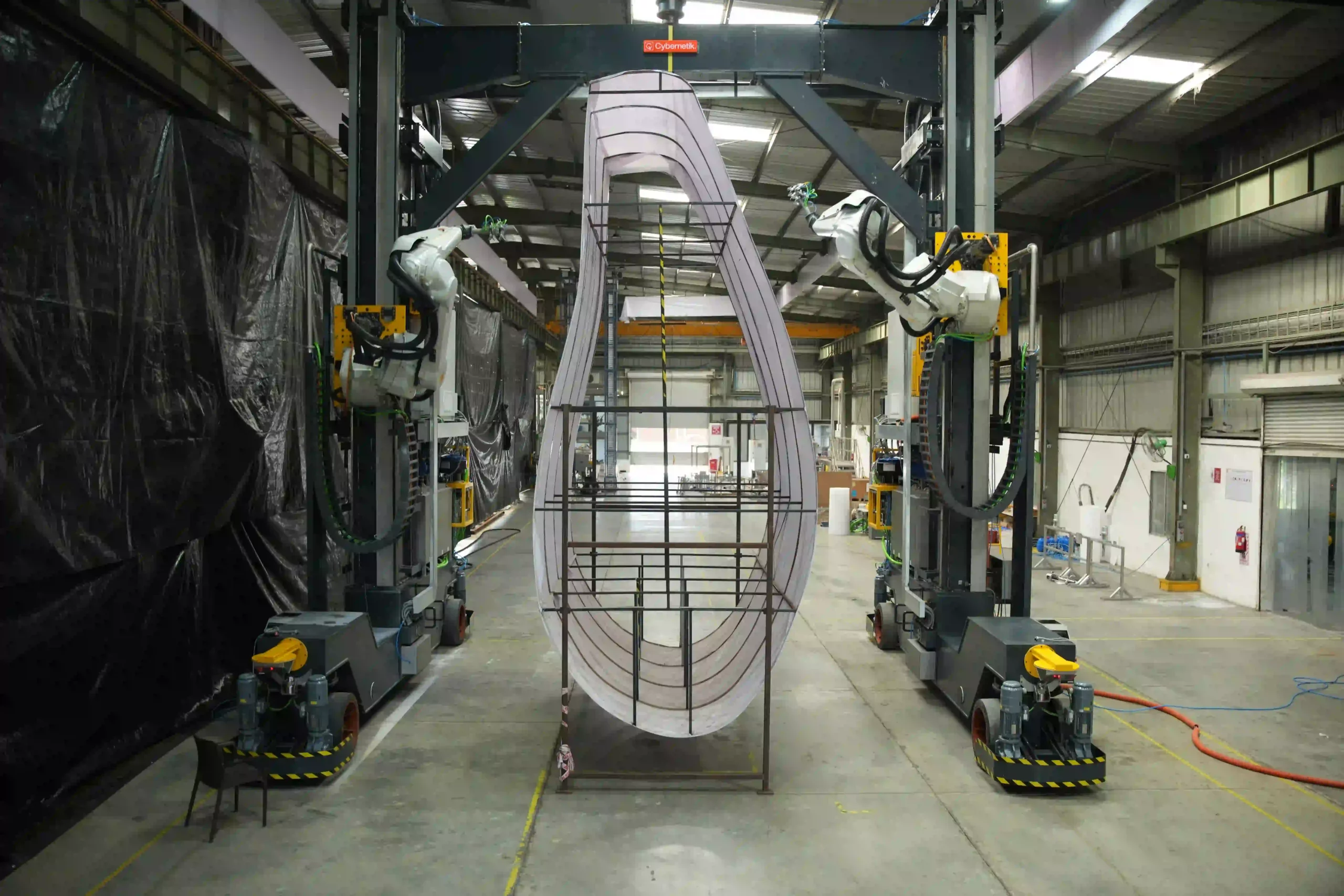
Cybernetik built the first robotic machining system of its kind for sawing, milling and drilling at the blade root end, covering root pitch circle diameters from 2,800 to 4,800 mm and blades up to 100 metres in length. The company has operated for more than three decades, is headquartered in Pune with offices in the United States and the UAE, and has installed over 6,000 systems across 30 plus countries, including more than 400 custom robotic automation solutions. In wind energy that work has been delivered for manufacturers including Siemens Gamesa and Suzlon. More background sits on the Cybernetik about page.