
Key takeaways
A catalytic converter is mostly empty space. The part that does the work is a honeycomb block with thousands of parallel channels running through it, and the chemistry happens in a coating only a few micrometres thick on the channel walls. That block is the substrate, and almost everything the converter is judged on comes back to it.
Substrates are often treated as a commodity ceramic component, bought on price and specification sheet. In practice, cell density, wall thickness and above all coating uniformity decide how quickly the converter lights off from a cold start, how much backpressure it imposes on the engine, and whether it still meets its emissions limit at 150,000 kilometres. Two substrates with identical dimensions and identical precious metal loading can perform very differently if one was coated evenly and the other was not.
This article covers what substrates are made of, how coated substrates are manufactured on a production line, where quality is won and lost during coating, and how requirements shift across heavy duty trucks, passenger cars and motorcycles. The manufacturing view here reflects how catalytic converter substrate coating systems are actually built and operated.
What the Substrate Does
The substrate is a carrier. Its job is to present the largest possible catalytic surface area to the exhaust stream while restricting flow as little as possible, and to survive thermal cycling between ambient temperature and roughly 900 degrees Celsius for the life of the vehicle.
On its own the substrate is catalytically inert. It becomes active only after washcoating, where a high surface area alumina slurry carrying platinum, palladium and rhodium is applied to the channel walls. The washcoat multiplies the effective surface area enormously, turning a smooth ceramic wall into a porous structure with far more sites where reactions can occur.
Those reactions are what the converter exists for. Carbon monoxide is oxidised to carbon dioxide, unburnt hydrocarbons are oxidised to carbon dioxide and water, and nitrogen oxides are reduced to nitrogen. Transport remains one of the largest contributors to urban air pollution, which is why substrate performance is a regulated characteristic rather than an engineering preference.
Ceramic and Metallic Substrates Compared
Two substrate families dominate production. Extruded cordierite ceramic accounts for the large majority of volume, while metallic foil substrates occupy applications where fast light off or vibration tolerance matter more than material cost.
| Attribute | Ceramic (cordierite) | Metallic (FeCrAl foil) |
|---|---|---|
| Construction | Extruded honeycomb block, fired | Corrugated and flat foil wound or stacked, then brazed |
| Typical cell density | 400 to 900 cpsi | 200 to 1,200 cpsi, higher densities achievable |
| Wall thickness | Thicker walls, typically 2 to 6 mil | Very thin foil, around 0.03 to 0.05 mm |
| Light off behaviour | Higher thermal mass, slower to reach operating temperature | Lower thermal mass, faster light off from cold start |
| Backpressure | Higher for a given cell density | Lower open frontal area loss, better flow |
| Durability profile | Excellent thermal stability, brittle under mechanical shock | Tolerant of vibration and shock, higher material cost |
| Common applications | Passenger cars, heavy duty diesel, most volume production | Motorcycles, small engines, close coupled and performance applications |
Cell density is quoted in cells per square inch. Higher cpsi gives more catalytic surface area and better conversion, but thinner walls and more channels also mean more backpressure and greater fragility during handling and coating. The specification is always a negotiated position between emissions performance, engine efficiency and manufacturability, not a single optimum.
How Coated Substrates Are Manufactured
Bare substrates arrive from the extrusion supplier. What happens next, on the coating line, is where the substrate becomes a functioning converter component. A modern automated line runs roughly the following sequence.
1. Washcoat blend preparation
The slurry is prepared in a series of tanks: premix, brewing and activation, with portable tanks for transfer. Solids loading, viscosity and particle size distribution are controlled here, and they determine how the slurry behaves inside a 900 cpsi channel. Blend variability at this stage is invisible until it shows up as coating weight scatter three stations later.
2. Loading, barcode marking and scanning
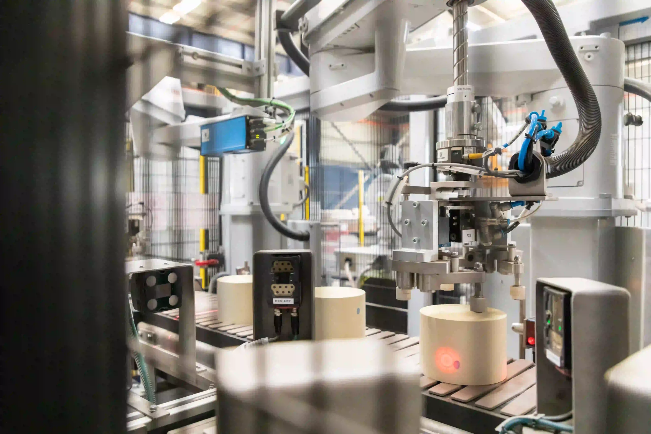
Each substrate is loaded, marked with a barcode and scanned before coating. This establishes the traceability record that every later measurement is written against. For a component subject to emissions regulation, batch level records are not enough. Regulators and OEM customers expect a part level history.
3. Coating
The coating machine applies washcoat into the channels, typically by drawing or pushing slurry through the block under controlled vacuum or pressure. Dose accuracy here directly sets precious metal loading, which is both the largest material cost in the part and the primary determinant of conversion efficiency.
4. Air stripping
An air stripper clears excess slurry from the channels. This is the step that prevents blocked cells. A blocked channel is dead volume: it contributes no conversion, raises backpressure and represents wasted precious metal. Strip pressure and duration have to be tuned to the cell density and slurry rheology in use.
5. Drying
The coated block passes through a dryer to remove water from the washcoat without disturbing its distribution. Drying too aggressively pulls the coating toward the block ends and thins the middle, which is a defect that no downstream weight check will catch because total mass is unchanged.
6. Inversion and second coating pass
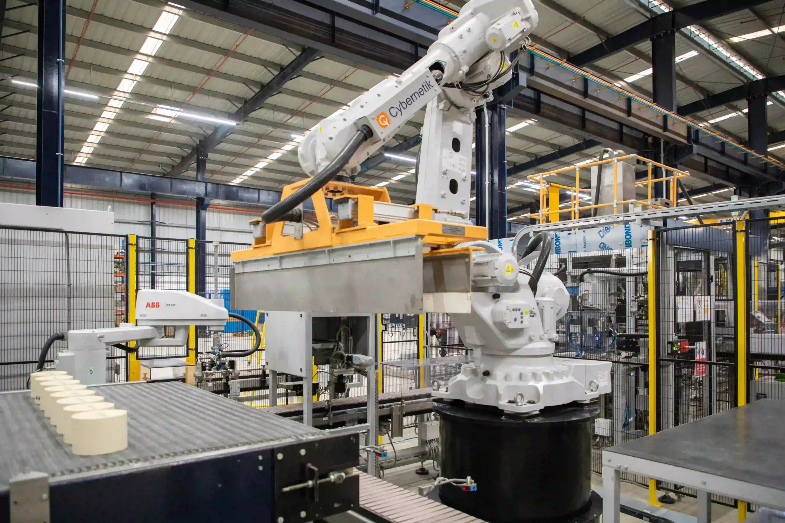
Many specifications require coating from both ends to achieve an even axial profile. Robotic pick and place handles the block, a turning station inverts it, and the coating and stripping sequence repeats. Handling here is delicate work: a coated, undried ceramic block is fragile and expensive.
7. Calcining and thermal processing
Calcining fixes the washcoat to the substrate wall and converts precious metal precursors into their active form. Time and temperature profiles are recipe controlled and logged. This is the step that turns a coated block into a catalyst.
8. Quality verification
Finished parts pass through a back pressure checking station to confirm no channel blockage, and through weighing stations that verify coating pickup. Three stage weight checking, before coating, after drying and after calcining, isolates which step caused a deviation rather than simply flagging that one occurred.
Where Substrate Coating Quality Is Won or Lost
Coating lines rarely fail outright. They drift, and the drift shows up in warranty data long after the parts have shipped. Four failure modes account for most of it.
 “The performance of a catalytic converter begins with the substrate, where precise coating, controlled thermal processing, and rigorous inspection transform a simple honeycomb into an effective emissions-control component.”

See it in action
Applications Across Vehicle Categories
Substrate requirements diverge sharply by application, and coating lines are configured accordingly.
Cybernetik’s Substrate Coating Automation
Cybernetik builds turnkey catalytic converter substrate coating systems that cover the full sequence above as one integrated line. The company has operated for over three decades, is headquartered in Pune with offices in the United States and the UAE, and has installed more than 6,000 systems across 30 plus countries. In the emissions control space that work has been delivered for manufacturers including BASF, Dinex, Mitsui Kinzoku, Süd-Chemie, DCL International and Ecocat India. More on the company sits on the Cybernetik about page.
The system scope spans four automation groups: