
Key takeaways
A wind turbine blade is a composite structure designed to survive twenty years of load reversal in open weather, built in a mould large enough to park a train in, and produced in numbers that make it a series manufacturing problem rather than a one off engineering exercise. Very few products combine those three conditions.
The result is an industry where material science, process control and manual craft sit uncomfortably alongside each other. A blade contains carefully engineered fibre architecture and resin chemistry, and a substantial share of it is still positioned by hand. Understanding blade manufacturing means understanding both halves.
This article covers the materials a blade is built from, the production sequence that turns them into a finished part, and an honest assessment of which stages are automated today and which are not. For the wider picture across nacelles, towers and castings, see the overview of wind turbine manufacturing.
What a Blade Is Made Of
Blade material selection is a continuous negotiation between stiffness, mass, fatigue life and cost. Each material earns its place in a specific location in the structure.
How the Structure Is Arranged
Understanding the process requires a quick picture of the architecture. A blade is essentially a hollow aerofoil shell stiffened internally. Two shells, pressure side and suction side, form the aerodynamic surface. Running spanwise inside each shell is a spar cap, a thick stack of unidirectional fibre that carries the bending load. Between the spar caps sit one or two shear webs, vertical panels that hold the two caps at a fixed separation and carry shear.
This is a beam wrapped in an aerodynamic skin. The spar caps are the flanges, the shear webs are the web, and the shells contribute torsional stiffness and shape. Almost every process decision in blade manufacturing exists to place those elements accurately and bond them reliably.
The Production Sequence
Mould preparation
Blades are made in heated female moulds, one per shell half. Release agent is applied, followed by gelcoat or an in mould coating that will become the blade’s outer surface. Mould temperature control matters throughout, because cure kinetics and therefore part quality depend on it.
Layup
Dry fabrics, core materials and prefabricated spar caps are positioned in the mould in a defined sequence. Ply boundaries, overlaps and orientations are specified precisely and verified before the mould is closed, because once resin is introduced nothing can be repositioned. This stage takes the largest share of labour hours in the entire turbine.
Vacuum infusion
The layup is sealed under vacuum bagging with flow media and resin feed lines, and resin is drawn through the dry stack. The flow front has to reach every fibre before the resin begins to gel, across a part that may be 80 metres long. Dry spots, voids and race tracking along unintended flow paths all originate here, and all become permanent.
Cure
Heat is applied through the mould to a controlled profile. Epoxy cure is exothermic, so thick sections such as the root laminate generate their own heat and require careful ramp control to avoid overheating and residual stress.
Web bonding and shell closing
Shear webs are bonded into one shell, adhesive is applied along the bond lines, and the second mould half closes onto the first. Bond line thickness has to stay within specification along the full span while two enormous mould halves come together. Too thin and the joint starves; too thick and it becomes brittle.
Demoulding and root end machining
The cured blade is lifted from the mould and the root is sawn to final length, face milled flat and perpendicular to the blade axis, and drilled for the hub bolt ring. Hole positions are held to within a millimetre on a pitch circle diameter of several metres. The complete eight stage sequence and its tolerances are covered in the guide to wind turbine blade root machining.
Finishing, inspection and testing
Surfaces are ground, filled, coated and fitted with leading edge protection. Non destructive inspection using ultrasonic testing, thermography and laser scanning checks laminate quality, bond line integrity and geometry. Blades are weighed and their mass moment measured, then matched into sets of three so the assembled rotor runs balanced. Design validation is handled separately through full scale static and fatigue testing of sample blades under IEC 61400 requirements.
 “The challenge in renewable energy manufacturing is no longer simply producing more – it is producing at scale with the precision, consistency, and traceability required for long-life, safety-critical products.“

See it in action
Where Automation Stands Today
Blade production is often described as either highly automated or barely automated, and neither is right. Automation has advanced unevenly, stage by stage, based on how tractable each operation is.
| Production stage | Automation status | What decides it |
|---|---|---|
| Fabric cutting and kitting | Largely automated | CNC cutting tables handle flat material predictably, so this was among the first stages to convert |
| Fabric and core layup | Mostly manual | Ply shapes change continuously along the span and material must conform to compound curvature that resists mechanised placement |
| Spar cap production | Increasingly automated | The shift to prefabricated pultruded carbon planks moved this stage out of the mould and into a controlled continuous process |
| Resin infusion | Automated delivery, manual setup | Resin metering and flow monitoring are machine controlled, but vacuum bagging and consumable placement stay manual |
| Cure | Fully automated | Mould heating and thermal profiles are recipe driven with logged parameters |
| Adhesive dispensing and closing | Partially automated | Robotic bead dispensing is established; alignment and closure still involve significant manual work |
| Root end machining | Fully automatable | A rigid, cured, dimensionally stable part with defined geometry, which is exactly what robotic machining handles well |
| Grinding, filling and painting | Mostly manual | Large curved surfaces, variable material removal and a difficult working environment; robotic sanding is emerging but not standard |
The pattern in that table is consistent. Stages involving rigid geometry, flat material or controlled thermal processes automated early. Stages involving flexible material conforming to compound curves, or variable material removal on large curved surfaces, have not. Layup and finishing are the two remaining labour concentrations, and both are the subject of active development across the industry.
Root machining sits in a different category from either. The part is cured, rigid and dimensionally stable, the geometry is defined, and the tolerance requirement is high enough that manual work struggles to hold it consistently. That combination makes it the clearest automation case anywhere in blade production, and it is why it converted to robotics faster than stages that are physically easier but geometrically messier.
Automating the Root End
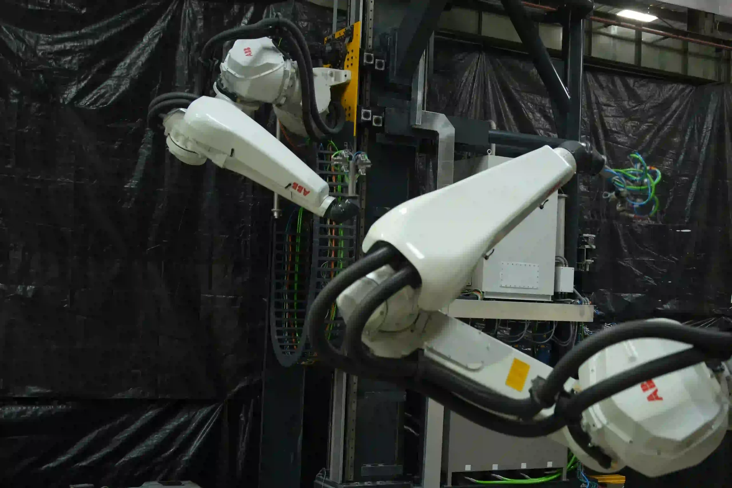
Cybernetik built the first robotic machining automation system of its kind for sawing, milling and drilling at the root end of wind turbine blades. The TurboMac range covers root pitch circle diameters from 2,800 to 4,800 mm and blades from 65 metres up to 100 metres, completing the full root operation in approximately eight to ten hours per blade. Details of the robotic root end machining system cover models, capacities and technical specifications.
The company has operated for more than three decades, is headquartered in Pune with offices in the United States and the UAE, and has installed over 6,000 systems across 30 plus countries, including more than 400 custom robotic automation solutions. In wind energy that work has been delivered for manufacturers including Siemens Gamesa and Suzlon. More background sits on the Cybernetik about page.