
Key takeaways
Every catalytic converter is a compromise between two things that pull in opposite directions. More surface area inside the brick means better conversion, and more surface area usually means narrower channels and more resistance to the exhaust flowing through. The engine pays for that resistance on every stroke, so the restriction a converter adds is something engineers design to a limit, manufacturers check on the line, and technicians test for in the field.
Catalytic converter backpressure is the resistance the converter adds to exhaust flow, measured as the pressure drop across it at a given flow rate. It is set mainly by cell density, wall thickness, washcoat thickness and how evenly gas is spread across the brick. In production it is checked on a flow bench to catch blocked or overcoated parts, and in service a rising reading usually means melting, face plugging or, in a diesel particulate filter, soot and ash build-up.
Why Backpressure Matters
The engine has to push its exhaust out against whatever sits in the way. Higher restriction means more work on the exhaust stroke, which costs fuel, and it leaves more hot exhaust in the cylinder, which affects combustion.
On turbocharged engines the effect is larger. Restriction after the turbine reduces the pressure ratio across it, so the turbo delivers less boost for the same exhaust energy. On engines with exhaust gas recirculation, backpressure also changes how much exhaust flows back to the intake, which affects emissions calibration. A converter that adds a little more restriction than designed is not just slightly less efficient. It moves the engine away from the conditions it was calibrated for.
That is why vehicle makers set an allowable pressure drop for each converter and why a part that exceeds it is rejected, even if its conversion performance is perfectly good.
Where the Restriction Comes From
| Source of backpressure | Why it adds restriction | Where it is decided |
|---|---|---|
| Channel friction | Gas drags along the channel walls for the full length of the brick | Cell density, channel size and brick length |
| Entry and exit losses | Gas squeezes into the channels and expands out of them | Wall thickness and open frontal area |
| Washcoat thickness | Coating narrows every channel and rounds its corners | Coating process and loading |
| Flow distribution | Gas crowds into the center of the brick if the inlet cone is poorly shaped | Can and inlet cone design |
| Blocked channels | Coating bridges or debris close channels completely | Coating, air stripping and handling |
| Wall-flow filtration | In a particulate filter, gas must pass through the porous walls | Filter design, soot and ash loading |
In a flow-through converter, most of the pressure drop comes from two places. Gas loses pressure squeezing into the channel openings at the front face and expanding out at the rear, and it loses more by friction along the channel walls. The first depends heavily on how much of the face is open, and the second on how narrow and long the channels are.
Cell Density and Wall Thickness
Substrate design is usually described by cell density, in cells per square inch, and wall thickness. Higher cell density gives more surface area for the catalyst, which improves conversion and light-off. It also makes each channel narrower. Thinner walls help recover some of the lost flow area, which is why higher cell densities nearly always come with thinner walls.
| Cell density | Wall thickness | Open channel width | Open frontal area |
|---|---|---|---|
| 400 cells per square inch | 0.10 mm | About 1.17 mm | About 85 percent |
| 600 cells per square inch | 0.10 mm | About 0.94 mm | About 81 percent |
| 600 cells per square inch | 0.08 mm | About 0.96 mm | About 86 percent |
| 900 cells per square inch | 0.05 mm | About 0.80 mm | About 88 percent |
The table shows the trade in practical terms. Moving from 400 to 600 cells per square inch at the same wall thickness reduces the open area and narrows every channel. Thinning the walls brings the open area back up. The 900 cell substrate has the narrowest channels and, because its walls are very thin, the largest open area of the four.
Thinner walls are not free. They make the substrate more fragile during coating, handling and canning, so each design balances surface area, flow, strength and light-off.
How substrates are made, and why cordierite and metallic options suit different applications, is covered in the article on catalytic converter substrates.
What the Washcoat Does to Flow
A bare substrate is not the finished part. The washcoat that carries the precious metals lines every channel, and it narrows them. It also collects in the corners of square channels, rounding them off, so the open shape becomes smaller and less square.
The effect on restriction is larger than the thin layer suggests. In the laminar flow typical of converter channels, pressure drop rises steeply as channels narrow, because the gas both speeds up and rubs against walls that are closer together. As a simplified illustration, a 600 cell substrate with 0.10 mm walls has open channels about 0.94 mm across. A washcoat about 25 microns thick on each wall reduces that to roughly 0.89 mm, which on its own raises the channel pressure drop by around a quarter. Real coatings are thicker in the corners than on the flat walls, so the actual figure depends on how the coating lays down.
This is why washcoat loading is controlled so tightly in production. Too little and the part may not convert well enough. Too much and it may restrict flow beyond the limit, and since the coating carries expensive precious metals, overloading costs money as well as performance.
Blocked Channels: The Hidden Defect
Average coating thickness is one problem. Channels closed off completely are another, and they are harder to see.
During coating, slurry is drawn or pushed through the channels and the excess is removed, typically by air stripping. If the slurry is too thick, the air flow is uneven or the part is not cleared properly, a film can bridge across a channel opening and dry in place. Once calcined, that channel is closed. A part with a cluster of blocked channels has less working surface and higher restriction, and nothing about it looks wrong from a normal viewing distance.
Debris adds to the risk. Chips from a damaged substrate edge, dust or fragments from handling can lodge in channels at any stage before canning. This is a large part of why gentle, consistent handling matters on a coating line.
Flow Distribution Across the Face
Exhaust does not naturally spread evenly across the face of a brick. It arrives through a pipe much narrower than the converter, and without a well-designed inlet cone, more of it flows through the center channels than the outer ones.
Uneven flow causes two problems. The center of the brick works harder and ages faster, so the converter loses performance sooner than its surface area suggests. And pressure drop is higher than it would be with even flow, because the center channels carry more than their share at higher velocity. Inlet cone shape, the distance between the inlet and the brick face, and sometimes diffusers are used to spread flow more evenly. This is decided in the can and system design rather than in the substrate.
Particulate Filters Are a Different Case
A diesel particulate filter is designed to restrict flow, because that is how it works. Alternate channels are plugged at opposite ends, so gas has to pass through the porous walls, leaving soot behind. A clean filter already has a higher pressure drop than a flow-through converter of similar size, and that pressure rises as soot accumulates.
That rise is useful. A differential pressure sensor across the filter lets the engine control system estimate how much soot is present and decide when to regenerate. After regeneration, the pressure should fall back toward the clean level. If it does not, the remaining restriction is usually ash from engine oil additives, which never burns off and eventually requires the filter to be cleaned or replaced.
Testing in Production
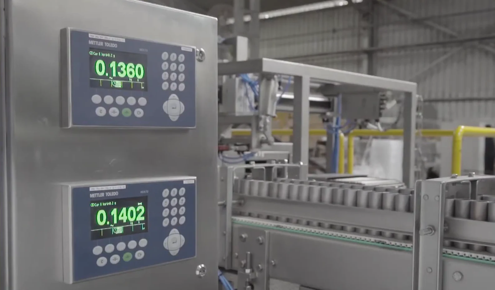
On a manufacturing line, backpressure testing is a check on each coated part rather than a design exercise. The goal is to catch overcoating and blocked channels before the part goes any further.
How the test works
The part is clamped into a fixture that seals around its edges so all air has to pass through the channels. A set flow of air is blown through it, and the pressure drop across the part is measured. The reading is compared against limits for that part number. Testing is usually done with air at room temperature, which is fast and repeatable, even though the converter will eventually work with hot exhaust.
Why test after calcining
The check is most useful once the coating is fixed in place. Testing a wet or dried-but-uncalcined part tells you less, because the coating can still change. Testing after calcining shows the restriction the finished part will carry into the can.
Pairing it with weight
Pressure drop and coating weight together tell a clearer story than either alone. A part that is the right weight but high in pressure drop probably has blocked channels or coating gathered in one area. A part that is heavy with high pressure drop is likely overcoated across the whole brick. A part that is light with normal pressure drop may be undercoated. Weighing at several stages, before coating, after the first coat and after calcining, lets the line see where the coating went.
Getting reliable readings
Fixture sealing matters more than any other detail. Air that leaks around the edge of the part rather than through it gives a falsely low reading, which can let a blocked part pass. Regular checks with reference parts of known pressure drop confirm the station is measuring correctly. Air temperature and supply pressure also affect the result, so a stable air supply is part of a reliable test.
 “Reliable substrate coating requires more than precise dosing. Gentle robotic handling, consistent air stripping, and automated inspection help protect fragile ceramic structures and reduce manufacturing defects.”

See it in action
Testing in Service
Workshops look for converter restriction when a vehicle loses power at higher speed, feels choked under load or shows poor fuel economy without an obvious cause.
Faults That Raise Backpressure in Service
| Fault in service | What causes it | What usually points to it |
|---|---|---|
| Melted substrate | Unburned fuel from misfires burning inside the brick | Loss of power at higher speed, rattling or a glazed face |
| Face plugging | Oil or coolant reaching the exhaust and fouling the inlet face | Oil consumption or coolant loss alongside rising restriction |
| Collapsed or moved brick | Mat failure, impact or overheating | Rattle, and sometimes debris further down the exhaust |
| Filter soot loading | Interrupted regenerations in short-trip use | Rising differential pressure and regeneration warnings |
| Filter ash loading | Oil additive residue that never burns | Pressure stays high even after successful regeneration |
| Damaged pipework | Crushed or kinked pipes and failed silencers | Restriction found upstream or downstream of the converter |
The converter is usually where the symptom appears, not where the cause sits. Replacing it without fixing the misfire, oil burning or coolant leak behind the fault tends to produce a second failure.
Designing for Lower Backpressure
Substrate Coating Lines from Cybernetik
Cybernetik builds substrate coating systems for heavy truck, passenger car and motorcycle catalytic converters, covering washcoat preparation, coating, drying, calcining and quality checks as one line. Lines have been built for DOC, DPF and SCR catalysts, and for metallic substrates using a rotary coater with a fixed volume doser and air stripper.
Several parts of that line address the issues in this article directly:
Drying runs at 150 to 200 degrees Celsius and calcining at 600 to 650 degrees Celsius, with a flip-over unit allowing parts to be coated from both ends. Cybernetik has been building custom automation for more than three decades, with design and build handled by one team through factory acceptance testing, installation and commissioning.