
Key takeaways
Bulk solids rarely move from one place to another at the same pressure. A silo may sit at atmospheric pressure while the pneumatic line below it runs under pressure. A dust collector operates under suction while the bin beneath it does not. Material has to pass between these zones without letting air rush through with it, and that is the job of a rotary airlock valve.
A rotary airlock valve is a feeding device in which a vaned rotor turns inside a closely fitted housing. Material falls into the pockets between the vanes at the inlet, is carried round and drops out at the outlet, while the tight clearance between rotor and housing limits air passing between the two sides. It is used to discharge silos, hoppers, cyclones and dust collectors, to feed pneumatic conveying lines and to meter powders and granules at a controlled rate.
This guide explains how a rotary airlock works, the main types and rotor designs, where they are used, how to size and select one, and what keeps it running reliably.
How a Rotary Airlock Valve Works
Picture a revolving door laid on its side. The rotor turns slowly, and each pocket passes under the inlet, fills with material, rotates to the bottom of the housing and empties into the outlet. The pocket then travels back up, empty, to fill again.
Two things happen at once. The valve meters material, since each turn delivers a roughly fixed volume, so feed rate follows rotor speed. And it forms a seal, because there is never an open path straight through the valve. At any moment, several vanes sit between the inlet and the outlet, each with only a small clearance to the housing wall.
Why it is never perfectly airtight
A rotary airlock limits air flow rather than stopping it completely. Air passes through two routes. Some leaks through the small gaps at the vane tips and sides. The rest is carried in the empty pockets as they return to the inlet, holding air at the outlet pressure and releasing it when they reach the inlet side.
That leakage matters most when the pressure difference is high or the material is fine. Air rising through the inlet can slow or stop material falling into the pockets. Many installations therefore include a vent that draws the leakage air away before it reaches the incoming product, which keeps throughput steady.
Parts of a Rotary Airlock Valve
| Part | What it does |
|---|---|
| Housing | The cast or fabricated body with an inlet on top, an outlet below and a bore the rotor turns inside |
| Rotor | A shaft with radial vanes that form pockets, usually six to ten, which carry material from inlet to outlet |
| End covers | Plates on each side of the housing that close the bore and carry the bearings and seals |
| Shaft seals | Packing, lip seals or air-purged seals that stop powder and air escaping along the shaft |
| Bearings | Mounted outside the product zone so they stay clean and support the rotor accurately |
| Drive | A geared motor, often with a variable frequency drive, turning the rotor at a controlled speed |
The clearance between rotor and housing is the single most important dimension in the valve. Tight clearances seal better but risk contact if the rotor expands with heat or a hard particle wedges in the gap. Looser clearances are more forgiving but leak more. Good designs choose the clearance for the material, pressure and temperature rather than using one figure for every application.
Types of Rotary Airlock Valves
The basic principle stays the same, but the housing and rotor are adapted to the job.
| Type | How it differs | Typical use |
|---|---|---|
| Drop-through | Material falls in from above and drops straight out below | Discharging hoppers, silos, cyclones and dust collectors |
| Blow-through | The conveying air passes through the rotor pockets and sweeps them clean | Feeding dilute phase pneumatic conveying lines, especially with sticky or fine powders |
| Side-entry | Material enters at an angle so pockets fill partly and the rotor does not shear particles | Pellets, granules and fragile products that would be cut or crushed |
| Quick-clean | Rotor slides out on rails or the end cover swings open without tools | Food and pharmaceutical plants with frequent product changes |
| Heavy-duty or abrasion-resistant | Thicker sections, hardened surfaces or replaceable liners | Cement, minerals, sand and other abrasive materials |
| Explosion-isolating | Built and certified to stop a flame or pressure wave passing through the valve | Combustible dusts where the valve forms part of the explosion protection |
Rotor designs
Within each type, the rotor itself can be configured to suit the product.
| Rotor option | When it helps |
|---|---|
| Open-end rotor | Simple and easy to clean, with vanes running to the end covers |
| Closed-end (shrouded) rotor | End discs reduce wear on the end covers with abrasive products and limit leakage |
| Adjustable or replaceable tips | Lets clearance be restored after wear without replacing the whole rotor |
| Flexible tips | Reduce shearing and jamming with lumpy or fibrous products, at the cost of a less tight seal |
| Scalloped (rounded) pockets | Help sticky powders release cleanly at the outlet |
| Reduced pocket volume | Gives finer control at low feed rates |
Where Rotary Airlock Valves Are Used
Rotary airlocks appear wherever powders and granules cross a pressure boundary or need a steady feed. They are one of a wider family of devices that control solids and liquids in a plant, set out in the guide to industrial valves.
Industries using them include food and flour milling, sugar, spices, dairy powders, pharmaceuticals, chemicals, plastics, cement, minerals and animal feed. The design changes with the product: a valve for milk powder needs hygienic construction and easy cleaning, while one for cement needs wear resistance above all.
Benefits of Using a Rotary Airlock
Rotary Airlock or Another Feeder?
A rotary airlock is not the only way to move material out of a vessel, and it is worth comparing it with the alternatives. For many applications the choice comes down to whether a pressure seal is needed, as covered in more detail in the article on flow control valves.
| Device | Strength | Limitation |
|---|---|---|
| Rotary airlock valve | Seals pressure while feeding at a steady, adjustable rate | Some air leakage is unavoidable, and clearances wear with abrasive products |
| Screw feeder | Accurate metering of powders over a wide range | Does not seal against pressure on its own |
| Double flap or dump valve | Good seal for coarse, hot or abrasive material | Feeds in batches rather than continuously |
| Slide gate or butterfly valve | Simple shut-off below hoppers and silos | Isolates flow but does not meter it |
Plants often combine devices. A slide gate above a rotary airlock lets the valve be removed for maintenance without emptying the silo, and a screw conveyor after the airlock can carry material on to the next process step.
 “Every bulk material handling application has unique operating demands. Selecting the right rotary airlock valve helps manufacturers achieve reliable flow, effective sealing, and consistent performance.”

See it in action
How to Size a Rotary Airlock
Throughput depends on four things: the volume of the rotor pockets per turn, the rotor speed, how full the pockets get, and the bulk density of the material. Multiplied together, they give the mass delivered per hour.
The figure that catches buyers out is fill efficiency. Pockets rarely fill completely, and they fill less as speed rises, because there is less time for material to drop in. Leakage air rising through the inlet reduces filling further. For this reason, a valve is usually sized so that it reaches the required rate at a moderate speed, with room to increase if needed, rather than running near its top speed all the time.
Bulk density deserves the same care. Aerated powder from a pneumatic receiver can be much lighter than the same powder settled in a bag. Sizing on the settled figure can leave the valve short of capacity in practice.
Selection Checklist
Installation Tips
Many airlock problems start with the way the valve is installed rather than the valve itself. A few details make a noticeable difference.
Maintenance and Troubleshooting
A rotary airlock usually tells you it is wearing before it fails. Throughput slowly drops, more air reaches the inlet, and dust appears around the seals. Checking these signs on a schedule is far cheaper than an unplanned stop.
| Problem | Likely cause | What usually fixes it |
|---|---|---|
| Throughput lower than expected | Air leaking up through the inlet, rotor running too fast, poor pocket filling | Vent the leakage air, slow the rotor, check bulk density and clearances |
| Material bridging above the valve | Leakage air fluidizing or packing the product in the inlet | Add a vent line or vent hopper above the inlet |
| Rising air leakage | Worn rotor tips or housing bore | Restore clearance by adjusting or replacing tips, or refurbish the housing |
| Rotor jamming | Lumps, foreign objects or thermal expansion closing the clearance | Screen the feed, add a lump breaker, choose clearances for the operating temperature |
| Dust escaping at the shaft | Worn seals or the wrong seal type for the pressure | Replace seals, or move to air-purged seals |
| Product buildup in pockets | Sticky or hygroscopic powder | Use scalloped pockets, a blow-through design or regular cleaning |
Rotation monitoring is a simple and useful addition. A speed sensor on the shaft confirms the rotor is turning, and stops upstream equipment if it is not, preventing a blocked inlet from backing material up into a collector or silo.
In automated plants, the valve’s speed, motor load and rotation signal can feed into the wider control system, linking it with conveyors, silos and packing. How these pieces fit together is covered in the guide to material handling automation.
Rotary Feeding Valves from Cybernetik
Cybernetik Technologies has been delivering turnkey automation since 1989, with more than 600 employees and over 6,000 projects installed. Its process division designs and builds powder and liquid handling systems for food, pharmaceutical and chemical plants, from bag and bulk bag unloading to storage, conveying, mixing and packing.
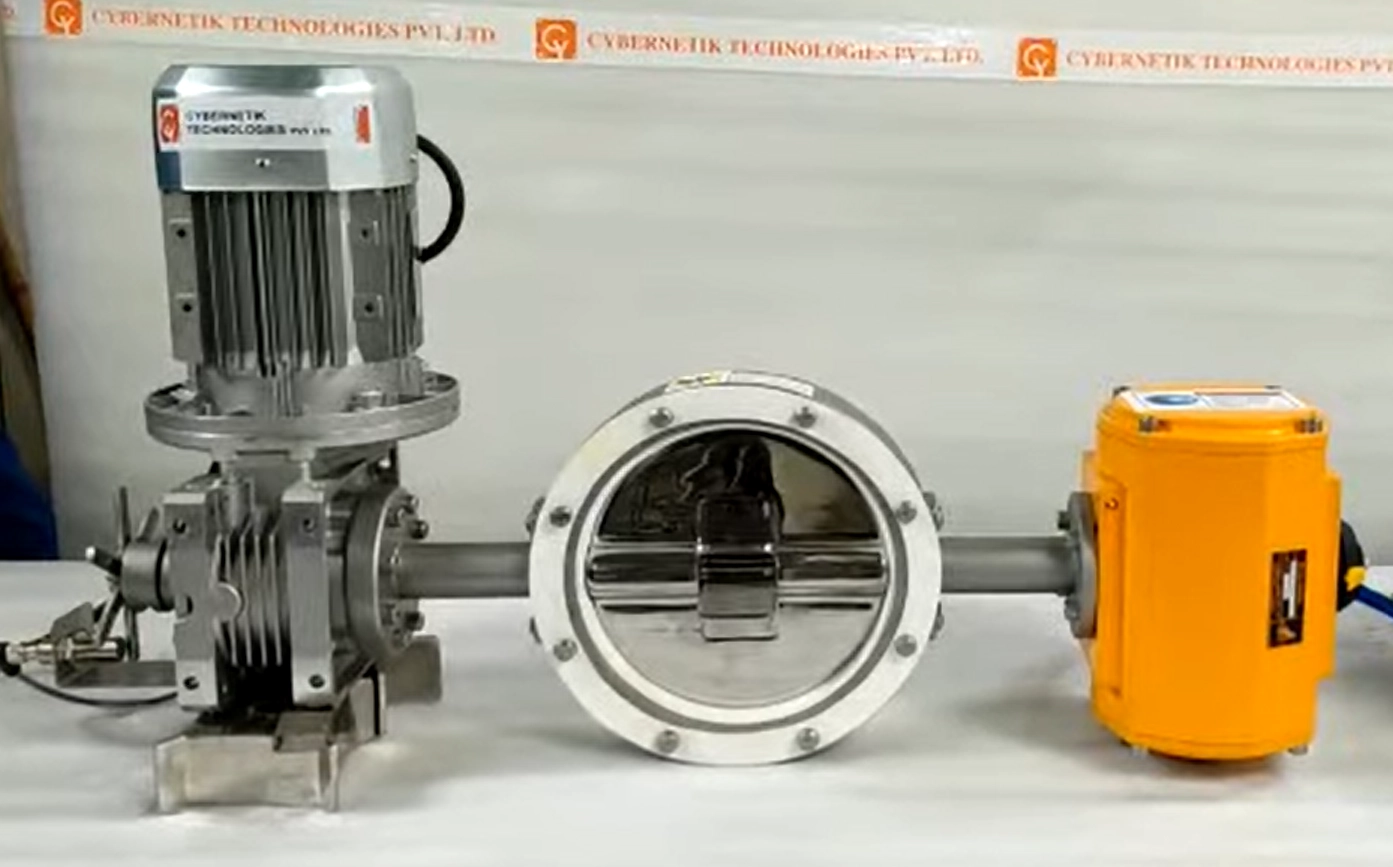
For controlled feeding of powders and granules, Cybernetik builds the CT Valve, a precision metering valve with electric actuation and a multi-blade or butterfly rotor, and the Combo Valve, which uses a butterfly rotor with a central feeder and separate actuators for fine and coarse flow.
| Cybernetik CT Valve | Specification |
|---|---|
| Model code | REFE-CTVA |
| Flow rate | 1,000 to 6,000 kg/hr, with customizable options |
| Inlet and outlet | NB 100 to NB 300 |
| Material of construction | SS304 and SS316 |
| Rotor options | Multi-blade or butterfly rotor |
| Flow control | Variable frequency drive |
| Sealing | Zero leakage, suitable for vacuum applications |
| Actuation option | Pneumatic, turning the rotor by 90° or 180° |
| Construction | Hygienic GMP design; ATEX construction for flame-proof areas |