
Key takeaways
Every wind turbine blade ends in a circle of bolts. Those bolts connect a composite blade to a steel pitch bearing, and between them they carry the whole blade’s load into the hub for twenty years or more.
As blades have grown longer, that circle has come under pressure. A longer blade puts a much larger bending moment into its root, which means the joint needs to carry more load. The obvious answer is more bolts, but there is only so much room around the circle. How a blade maker deals with that limit comes down largely to which kind of root joint it uses.
The two main options are the T-bolt joint and the embedded insert joint. This article explains how each one works, where each fits, and what each asks of manufacturing.
Why the Root Is the Hardest Joint on the Blade
The root is where two very different materials have to share a very large load. The blade is a fiber composite: strong along its fibers, much less so across them, and sensitive to holes and stress concentrations. The hub side is steel, which behaves predictably and tolerates bolted connections well.
Joining them means getting a concentrated bolt load into a laminate without damaging it, and doing so under constant cycling. A blade turning through its working life sees an enormous number of load cycles as it rotates, meets gusts and passes the tower. The root joint has to survive all of them.
That is why root design and root machining get so much attention, a subject introduced in the article on wind turbine blade root manufacturing. The joint type decides how the load is passed across, and that shapes everything from wall thickness to how the root is machined.
How a T-Bolt Joint Works
The T-bolt joint, also called a cross-bolt or barrel nut joint, is the longer-established of the two.
After the blade is molded, two sets of holes are machined into the root. Radial holes are drilled through the side wall of the root, and a cylindrical steel barrel nut is placed in each one. Axial holes are then drilled into the root face, each meeting a barrel nut at right angles. A stud bolt passes through the pitch bearing, down the axial hole and screws into the barrel nut.
When the bolt is tensioned, the barrel nut presses against the laminate around its hole. That bearing contact is how load passes from steel into composite. The arrangement is simple, uses relatively inexpensive parts and has a long track record, which is a large part of why it remains so widely used.
Its main constraint comes from that same bearing contact. The laminate around each barrel nut has to be thick enough to carry the load without crushing, and there has to be enough material between neighboring barrel nuts. That sets a minimum spacing between bolts, and it pushes the root wall to be thick.
How an Embedded Insert Joint Works
An embedded insert joint takes a different approach to getting load into the laminate.
Instead of a barrel nut, each bolt screws into a threaded metal insert set into the root wall, running parallel to the blade axis. Load passes from the insert into the surrounding laminate through shear along the length of the insert rather than through bearing at a single point. Spreading the load that way reduces peak stress in the composite.
There are two broad ways of getting the inserts in. They can be laminated into the root during molding, becoming part of the structure as it is built, or they can be bonded into holes drilled after molding. The first ties insert quality to the molding process; the second adds a drilling and bonding step but separates it from layup.
Because load is spread along each insert rather than concentrated around a nut, inserts can sit closer together and the root wall can be thinner. Both of those matter a great deal on large blades.
The Two Compared
| T-bolt joint | Embedded insert joint | |
|---|---|---|
| How load gets into the laminate | A steel barrel nut bears against the laminate through a radial hole | A threaded metal insert passes load into the laminate by shear along its length |
| When it is made | Machined after the blade is molded | Inserts laminated in during molding, or bonded into holes afterward |
| Root wall thickness | Thick, to carry bearing load around each barrel nut | Thinner, since load spreads along the insert |
| Bolt spacing | Limited by the size of the barrel nuts and the laminate between them | Closer spacing possible, so more bolts on the same circle |
| Manufacturing complexity | Simpler and well established | More demanding, especially insert positioning and bonding |
| Hardest thing to verify | Hole position and drilling damage | Bond quality around each insert, which sits inside the laminate |
| Repair | Relatively accessible | Difficult once inserts are in place |
| Typical home | Widely used across many blade sizes | Increasingly common on longer, more heavily loaded blades |
The Bolt Count Problem
This is where the choice becomes most interesting, and it explains why embedded inserts have become more common as blades have lengthened.
The load a root joint can carry depends heavily on how many bolts it has. With a T-bolt joint, bolt spacing is limited by barrel nut size and the laminate needed between them. To add bolts, the pitch circle has to grow, which means a larger root diameter, a larger bearing and a larger hub, all of which add cost and weight well beyond the blade itself.
Embedded inserts ease that limit. Closer spacing means more bolts fit on the same circle, so a joint can carry more load without growing the root. For very long blades, where root moments are highest, that can make the difference between a root that fits an existing hub design and one that forces a larger one.
That does not make inserts universally better. For many blades the T-bolt joint carries the load comfortably, costs less and is simpler to make. The pressure toward inserts builds as blades get longer and loads rise, rather than applying across the board.
What Each Means for Manufacturing
The two joints ask very different things of the root machining and finishing stage.
| Machining task | T-bolt root | Embedded insert root |
|---|---|---|
| Root face milling | Needed, to make a flat, square mating face | Needed, for the same reason |
| Axial drilling | Core task: a hole from the face for each stud | Only for bonded-in inserts; not needed where inserts are laminated in |
| Radial drilling | Core task: a cross hole for each barrel nut, meeting the axial hole | Not needed |
| Position check | Pitch circle, hole spacing and perpendicularity | Insert position and perpendicularity after molding or bonding |
| Main risk | Misaligned holes and fiber breakout at drill exit | Inserts shifted during molding or poorly bonded |
 “T-bolt joints depend on precise drilling, while embedded inserts demand controlled positioning and bonding. In both designs, manufacturing quality directly influences joint reliability.”

See it in action
T-bolt roots are a drilling problem
For a T-bolt root, precision drilling is the heart of the job. Each axial hole has to meet its barrel nut hole accurately, the holes have to sit on the right pitch circle at the right spacing, and they have to run square to the root face. A small error in any of those loads the bolt unevenly, and uneven bolt loading is a fatigue problem waiting to develop.
Drilling composite also brings its own risk. Fibers can break out or the laminate can delaminate where a drill exits, especially on the radial holes. Tool condition, feed and support behind the exit point all affect how clean each hole is.
Insert roots are a positioning and bonding problem
For a laminated-in insert root, much of the difficulty moves upstream into molding. Inserts have to stay exactly where they were placed while resin flows and cures around them, and any that shift end up out of position with no easy correction afterward. The root face still has to be milled flat and square, and insert position has to be checked once the part is out of the mold.
For bonded-in inserts, the drilling returns, followed by a bonding step whose quality decides the strength of every connection.
Inspection and Quality
The two joints differ sharply in how easy they are to check.
With a T-bolt joint, most of what matters can be measured directly. Hole positions, pitch circle, spacing and perpendicularity can all be inspected on the finished root, and drilling damage at hole exits can usually be seen or detected.
With an embedded insert joint, the most important quality attribute sits inside the laminate: how well each insert is bonded to its surroundings. A void or disbond around an insert weakens that connection and may not be visible from outside. Ultrasonic methods can inspect bond quality, but it takes more effort and more interpretation than measuring a hole. That is one reason insert roots put greater weight on process control during manufacture rather than relying on inspection afterward.
Repair and Service Life
Repairability tends to favor the T-bolt joint. Its components are more accessible, and damage around a hole is easier to assess than a failing bond inside the laminate.
Repairing an embedded insert that has lost its bond is much harder, because the insert is part of the structure. That puts extra importance on getting insert roots right the first time, which again points back to process control and positional accuracy during manufacture.
Choosing Between Them
The choice is usually made at the blade design stage rather than on the shop floor, and it tends to follow a few factors.
Both remain in wide use, and many manufacturers run both across different blade models. How the root fits into the wider blade production sequence is covered in the guide to wind turbine blade manufacturing.
Root Machining at Cybernetik
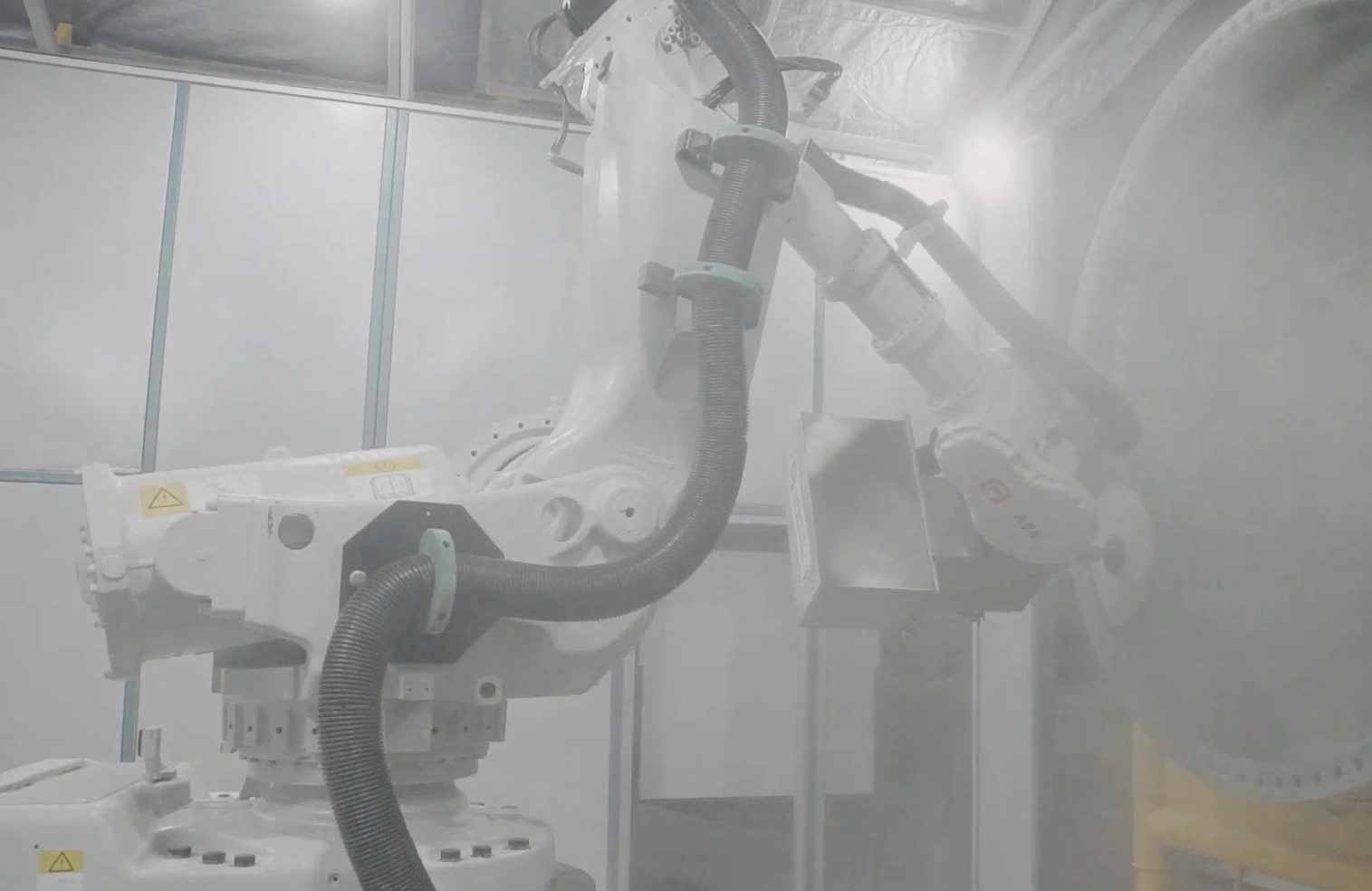
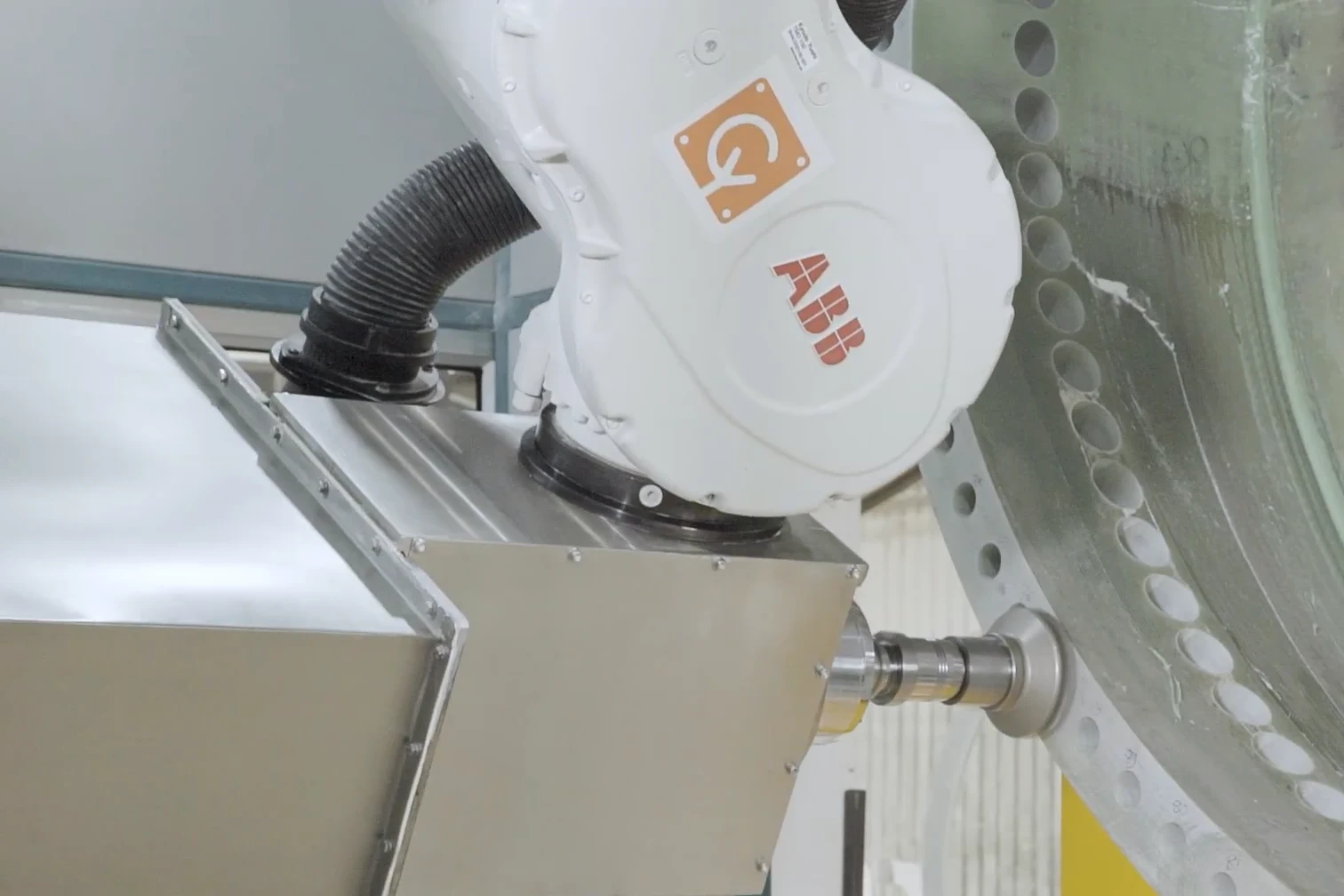
Cybernetik builds blade root machining systems within its wind energy automation range, designed for the face milling and drilling that roots depend on.
| Cybernetik blade root machining | Specification |
|---|---|
| TurboMac 3000 | Pitch circle diameter 2,800 to 3,000 mm, for blades of around 65 to 70 m |
| TurboMac 4800 | Pitch circle diameter 3,000 to 4,800 mm, for blades up to around 100 m |
| Pitch circle accuracy | PCD within plus or minus 1 mm |
| Face milling | Milling flatness within 0.500 mm |
| Hole accuracy | Hole perpendicularity within plus or minus 0.250 mm |
| Wind customers | Machining work delivered for blade makers including Siemens Gamesa and Suzlon |
Those tolerances matter most on T-bolt roots, where the accuracy of every hole decides how evenly the bolts share load. Pitch circle accuracy keeps the pattern matched to the bearing, face flatness gives an even mating surface, and hole perpendicularity keeps each bolt loaded along its axis rather than at an angle. For any specific root design, including insert-based roots, it is worth confirming the machining scope directly with Cybernetik’s engineers.
Cybernetik has been building automation for more than three decades. It is headquartered in Pune with facilities in Gujarat and Raigad and offices in the United States and UAE, and has installed over 6,000 systems in more than 30 countries, including over 400 custom robotic solutions. More background is on the Cybernetik about page.