
Key takeaways
Clean-in-Place is usually described in terms of hardware: tanks, pumps, spray balls, a control panel. But the equipment does not clean anything. The process does, and two plants running identical CIP skids can produce very different hygiene outcomes depending on how their cycles are designed and controlled.
That matters commercially, because cleaning consumes production time, water, chemicals and energy on every changeover, in some plants several times a day. A cycle longer or more aggressive than the soil requires is money spent every run. One that is too gentle is a contamination event waiting to happen.
This article covers what actually removes soil from a process line, how cycle stages are sequenced and why, the flow conditions that determine whether cleaning solution does any work at all, and how cleaning is verified afterwards. For the equipment side, tank configurations, pumps and controls, see the guide to Clean-in-Place systems.
Process Versus System
A CIP system is the physical installation: solution tanks, supply and return pumps, heat exchangers, valves, spray devices and the control layer that runs them. A CIP process is the recipe that installation executes for a specific product, on a specific circuit, against a specific soil.
One system typically runs many processes. Cleaning a chocolate line after a fat-rich product is a different sequence from cleaning the same tank after a fruit preparation, and treating them identically means one of the two is wrong. Recipe-driven control exists because the process, not the system, changes between products.
The Four Variables That Do the Cleaning
Every cleaning outcome is produced by four variables working together. Cleaning science has described this relationship for decades, and it is the single most useful framework for anyone designing or troubleshooting a CIP cycle.
The practical value of the framework is that the four are interchangeable within limits. Reduce contact time and you must raise temperature, concentration or flow to compensate. Plants that shorten cycles to recover production hours without adjusting anything else are not saving time; they are reducing cleaning performance and finding out later.
Substitution has boundaries, though. No amount of time or concentration cleans a fat soil below its melting point, and no amount of chemistry compensates for a section of pipe where flow is laminar. Those are threshold conditions rather than trade-offs.
Soil Types and Matching Chemistry
Cycle design starts with identifying what is actually on the equipment surface. Different residues respond to entirely different chemistry, and sequencing them incorrectly can make removal harder rather than easier.
| Soil type | Where it comes from | What dissolves it | Cycle implication |
|---|---|---|---|
| Sugars and carbohydrates | Confectionery, beverages, sauces, syrups | Water alone in most cases | Removed largely by pre-rinse; heavy caustic is unnecessary |
| Fats and oils | Dairy, chocolate, fat processing, snack frying | Hot alkaline solution through saponification | Temperature matters more than concentration; below the fat melting point nothing works |
| Proteins | Dairy, meat, egg, plant protein processing | Alkaline solution, sometimes with additives | Denatures and hardens if heated before removal, so pre-rinse temperature must stay moderate |
| Mineral salts and scale | Hard water, dairy stone, calcium deposits | Acid solution such as nitric or phosphoric | Needs a dedicated acid stage; alkali alone will build scale over time |
| Biofilms | Microbial growth in low flow or dead areas | Mechanical action plus oxidising sanitiser | Chemistry alone will not clear it; flow velocity is the real control |
The protein row explains a common and expensive mistake. Heating a protein soil before rinsing it denatures the protein and bonds it to the stainless surface, at which point removal takes far longer than it would have taken cold. This is why pre-rinse temperature is specified rather than simply set to whatever hot water is available.
The CIP Cycle, Stage by Stage
1. Pre-rinse
Water flushes loose product and soluble residue out of the circuit before any chemistry is introduced. A well executed pre-rinse removes the large majority of total soil load and directly reduces how much caustic the next stage consumes. Rinse water is usually sent to drain or to a recovery tank, and rinse endpoint is judged by conductivity or turbidity rather than by a fixed timer.
2. Alkaline wash
Caustic solution, commonly sodium hydroxide at one to two percent and typically circulated at 70 to 80 degrees Celsius, removes fats and proteins. Fats are converted to soluble soaps through saponification, which is why this stage is temperature sensitive rather than concentration sensitive. Solution is recirculated through the circuit for a defined period and returned to the alkali tank if the system reuses it.
3. Intermediate rinse
Water removes residual caustic before the next chemical stage. Skipping or shortening this rinse causes the following acid stage to neutralise against leftover alkali rather than attacking scale, which wastes chemical and leaves mineral deposits behind.
4. Acid wash
Nitric or phosphoric acid, typically at lower concentration and moderate temperature, dissolves mineral scale, water hardness deposits and dairy stone. Not every cycle needs an acid stage on every run, but circuits running on hard water or handling dairy will accumulate scale steadily without one, and that scale eventually shelters microbial growth.
5. Sanitisation
Hot water, steam or a chemical sanitiser reduces microbial load on cleaned surfaces. This stage sanitises; it does not clean. Sanitiser applied to a surface that still carries soil is largely wasted, because residue shields organisms from contact.
6. Final rinse and changeover
Potable or purified water removes all chemical residue, verified by conductivity and pH returning to feed water values. In systems with recovery, this water is often captured for use as the next cycle’s pre-rinse, which is one of the more effective water reduction measures available.
 “The right CIP cycle balances cleaning performance with production efficiency, ensuring that every additional minute, litre of water, and kilogram of chemical delivers measurable sanitation value.”

See it in action
Flow, Coverage and Dead Legs
The mechanical action variable is where most underperforming CIP processes actually fail, and it is rarely the first thing anyone checks.
In pipework, cleaning depends on turbulent flow. Below roughly 1.5 metres per second, flow near the pipe wall becomes too gentle to shear soil away, and the solution passes through the line without doing useful work. It looks like cleaning is happening because solution is circulating and chemistry is correct, but the pipe wall never experiences the scrubbing action the cycle assumes.
In vessels, coverage is the equivalent concern. Static spray balls flood surfaces and rely on a falling film, which suits light soils and large tanks. Rotary jet heads deliver concentrated impingement in a pattern and handle heavier soils, at the cost of a longer cycle. Neither reaches surfaces shadowed by agitators, baffles or internal fittings, which is why vessel internals belong in the specification when the cleaning device is chosen.
Dead legs are the third failure point. Any branch, sample port or blanked-off section where flow stagnates will not clean, whatever the rest of the circuit does. Hygienic design practice limits branch length to roughly three pipe diameters, because beyond that the solution in the branch does not exchange with the flowing stream.
Single-Use, Reuse and Recovery
Single-use cycles send every solution to drain after one pass. They are simple, eliminate any risk of carryover between circuits, and suit pharmaceutical applications and allergen changeovers where cross-contamination consequences are severe.
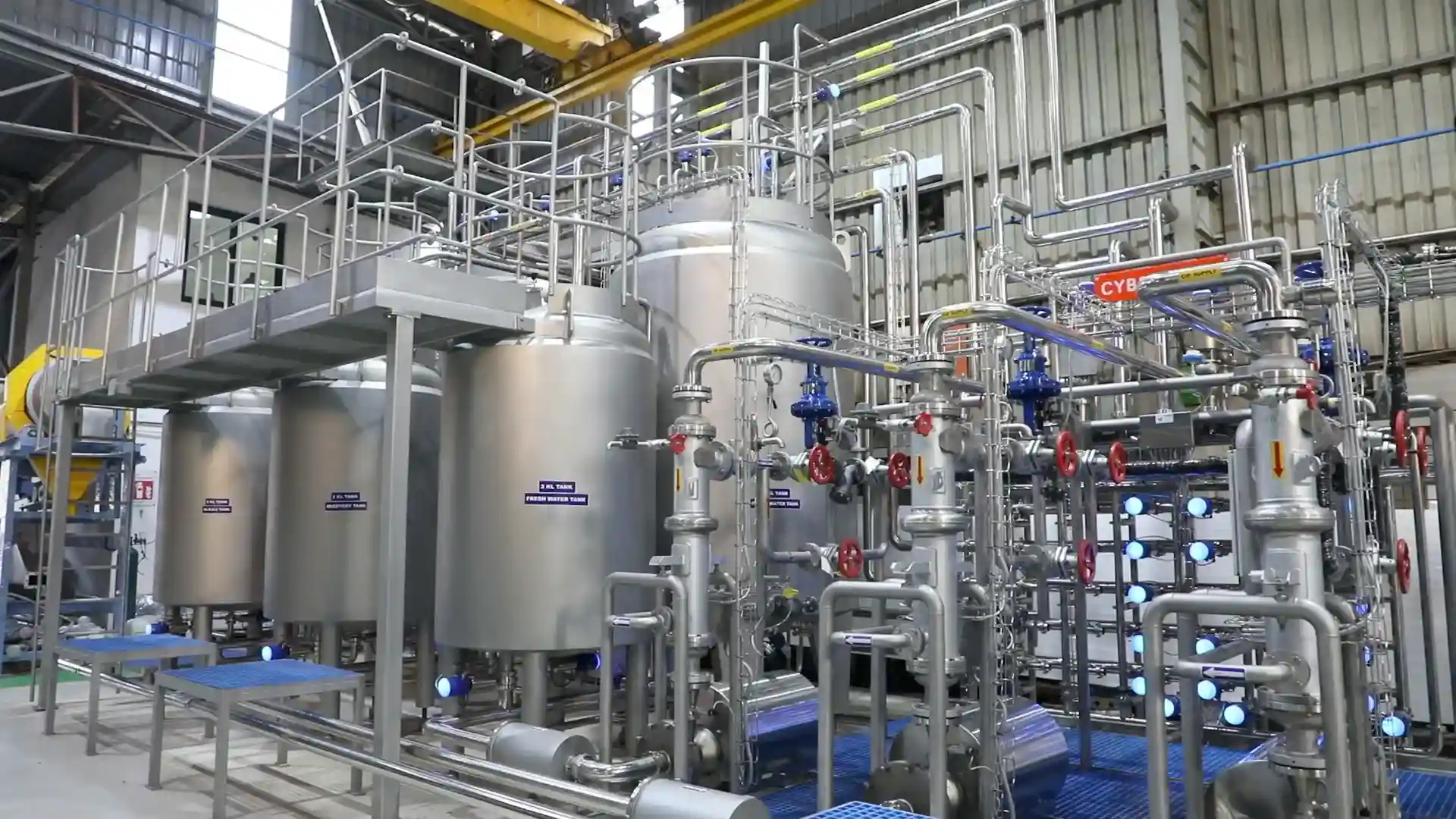
Reuse systems return caustic and acid to dedicated tanks, replenish them to target concentration, and use them again across many cycles. Water, chemical and heating costs fall substantially. The trade-off is that solution condition has to be monitored, since a recovered caustic tank accumulates soil load over time. Multi-tank configurations on Cybernetik CIP systems separate water, acid, alkali and recovered water for exactly this reason.
Verifying That Cleaning Actually Happened
A cycle that ran is not a cycle that worked. Verification operates at three levels of rigour.
Pharmaceutical manufacturing goes further, requiring formal cleaning validation: acceptance limits calculated from maximum allowable carryover, demonstrated across consecutive successful runs and documented for inspection. Food plants operating to GMP standards, including automated lines such as ready-to-eat food processing systems, increasingly apply comparable discipline.
Where CIP Processes Go Wrong
Cybernetik’s Approach to CIP Automation
Cybernetik builds automated CIP systems designed around recipe-driven process control rather than fixed cleaning cycles, in single-tank and multi-tank configurations with capacities up to 8,000 litres and GMP-compliant stainless construction in SS304 or SS316.
The company has operated for more than three decades, is headquartered in Pune with offices in the United States and the UAE, and has installed over 6,000 systems across 30 plus countries, including more than 400 custom automation solutions across food, pharmaceutical, chemical and industrial processing. Further background sits on the Cybernetik about page.