
Key takeaways
Paddle mixers occupy a useful middle position in industrial mixing. They are gentler than ribbon blenders, faster than tumble blenders, and in twin-shaft form they mix in a fraction of the time either takes. That combination makes them the right answer for a specific set of problems and the wrong answer for several others.
The difficulty in selection is that the term covers two genuinely different machines. A single-shaft paddle mixer and a twin-shaft paddle mixer share a name and a paddle, and almost nothing else about how they perform.
This guide covers how paddle mixing works, the single versus twin shaft decision, where paddle beats ribbon and where it does not, and what to specify. The comparison across the whole mixing field sits in the guide to industrial blenders.
How a Paddle Mixer Works
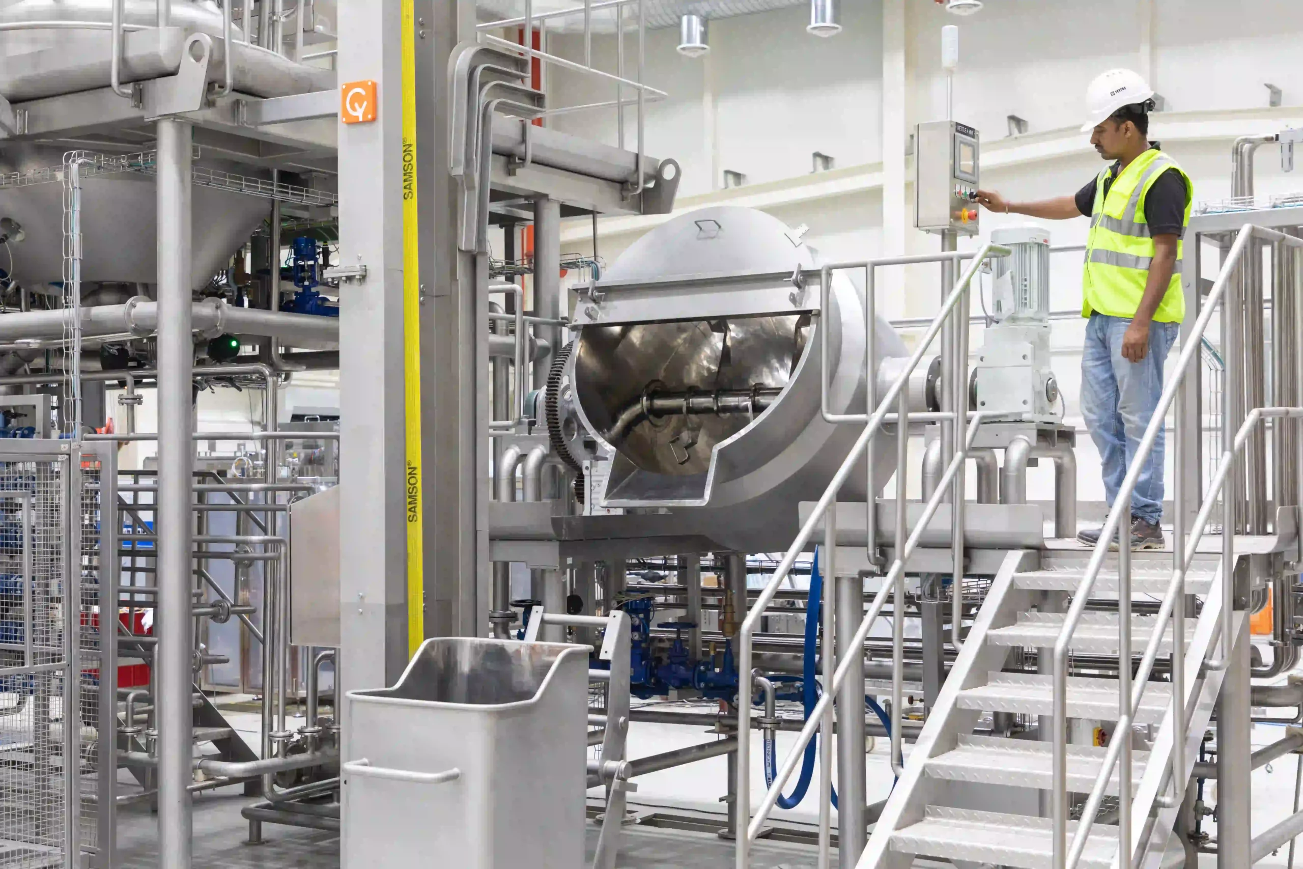
Paddles are individual blades mounted on arms along a horizontal shaft, set at an angle to the direction of rotation. As the shaft turns, each paddle lifts material and throws it forward and sideways, and the combination of many paddles at different positions produces movement in three directions rather than one.
That differs from a ribbon blender, where a continuous helical ribbon moves material steadily along the trough. A ribbon conveys as much as it mixes; paddles disturb rather than convey. The consequence is that paddle mixing is gentler on the product, since material is thrown and folded rather than dragged along a wall, and it is less prone to the shear that damages friable particles.
Paddle angle is usually adjustable, which allows the balance between axial movement along the trough and radial movement across it to be tuned for a particular material. That adjustability is worth confirming rather than assuming, since fixed-angle designs are cheaper and less adaptable.
Single Shaft or Twin Shaft
| Single shaft paddle | Twin shaft paddle | Comment | |
|---|---|---|---|
| Mixing action | Paddles lift and fold material along a horizontal trough | Counter-rotating shafts create an overlapping fluidized zone | The twin-shaft zone is what enables very short cycles |
| Typical mix time | Several minutes | Frequently under two minutes | The largest practical difference between them |
| Segregation resistance | Good | Very good, because particles are briefly weightless in the overlap | Matters most with wide density or size differences |
| Minor component handling | Adequate with sufficient time | Strong, including additions at fractions of a percent | Twin shaft suits premixes and micro-ingredients |
| Liquid addition | Possible with spray bars | Well suited, with the fluidized zone distributing liquid rapidly | Both need spray design rather than a single injection point |
| Capital and power | Lower | Higher on both counts | Twin shaft costs more and returns it in cycle time |
| Discharge | Plug or slide valve along the trough | Full-length bomb-bay doors | Bomb-bay discharge empties in seconds, which matters at short cycles |
The middle rows are where the decision usually resolves. If mixing time is not constraining production and segregation is not a problem with your materials, a single-shaft machine does the job at lower cost. If either of those is true, twin shaft changes the arithmetic substantially.
The Fluidized Zone
This deserves explaining properly, because it is the mechanism behind twin-shaft performance and it is not obvious from a drawing.
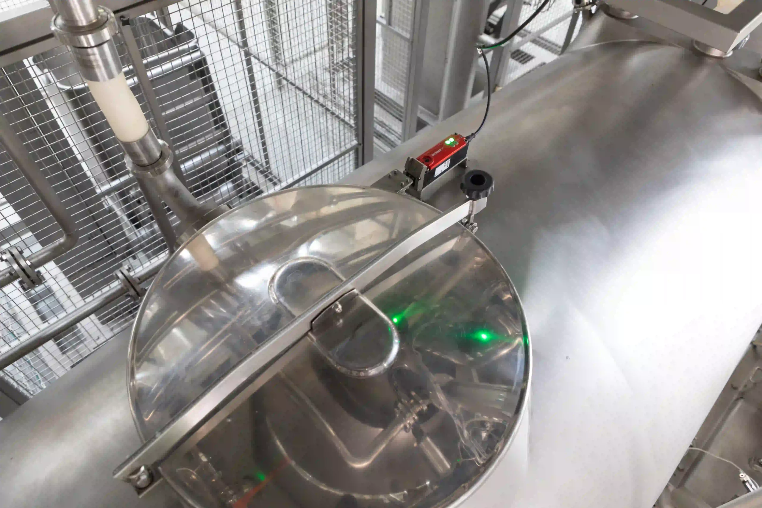
Two shafts rotate toward each other, and their paddle paths overlap in the center of the trough. In that overlap region, material thrown by one set of paddles meets material thrown by the other, and for a moment particles are held in suspension rather than resting on anything. The condition is often described as a weightless or fluidized zone.
What matters is what happens to segregation there. Segregation in powder mixing is driven largely by particle size and density differences acting under gravity: heavier or larger particles settle, finer ones migrate. In a zone where particles are momentarily suspended, those gravity-driven effects are suppressed, so components that would normally separate stay together long enough to distribute.
That is why twin-shaft mixers achieve high homogeneity in cycles measured in tens of seconds rather than minutes, and why they handle formulations with wide density differences or very small minor components that other geometries struggle with. It is also why they cost more: two shafts, two drives and a heavier structure.
Paddle Against Ribbon
The two are the most commonly compared industrial mixers, and each has a clear domain.
Where paddle wins
Where ribbon wins
Batch or Continuous
Paddle geometry adapts well to continuous operation, which is less true of most other mixer types.
A continuous paddle mixer receives metered streams of each component at one end and discharges a blended stream at the other, with mixing occurring during the residence time inside the trough. It removes the fill, mix and discharge cycle entirely, reduces work in progress and needs less floor space per ton produced.
The control burden shifts, though. With no batch to sample and release, uniformity depends entirely on feeder accuracy and residence time. Loss-in-weight feeders ahead of the mixer become as critical as the mixer itself, and a feeder drifting produces an out-of-specification product continuously rather than one bad batch.
The practical test is campaign length. A plant running long runs of one formulation should evaluate continuous seriously. A plant changing formulation several times a day is almost always better served by batch.
 “A correctly mixed batch can still lose quality during discharge, making complete and controlled discharge an essential part of mixer design rather than an afterthought.”

See it in action
Liquid Addition
Adding liquid to a dry mix is one of the more common reasons a paddle mixer is chosen, and it is worth specifying properly rather than treating as a nozzle in the lid.
Liquid meeting a slow-moving powder mass forms wet agglomerates that then have to be broken down, which either takes mixing time or does not happen at all. Spray bars distributing liquid across the width of the moving material, rather than a single injection point, prevent that. Where formulations carry significant liquid, chopper blades mounted in the trough wall break agglomerates as they form.
Sequence matters too. Liquid added before the dry components are distributed produces a mix with wet and dry regions that never fully reconcile, so recipe control that sequences additions correctly is part of the specification rather than an operational preference.
Fill Level and Sizing
Every mixer has a working fill range narrower than its gross volume, and paddle mixers are no exception.
Overfilling is the more common error. Paddles need space to throw material; a trough filled beyond its working level cannot develop the three-dimensional movement the geometry depends on, and in a twin-shaft machine it cannot form the fluidized zone at all. The mixer runs, looks correct and produces poor uniformity, and extending mix time does not help because the mechanism is not operating.
Underfilling wastes capacity and, in twin-shaft designs, may leave material below the overlap region.
Size against actual batch size and the working fill range rather than against gross volume, and where batch sizes vary widely, consider two machines rather than one operating at both extremes.
Specification Checklist
Applications
Mixing Equipment from Cybernetik
Cybernetik builds mixing equipment across geometries and specifies it against the material and the batch requirement rather than from a single product line. The continuous paddle mixer covers steady-state production, while ploughshare mixers at 500 to 5,000 liters handle three-dimensional mixing with liquid addition where a fluidized action is required in batch form.
| Cybernetik mixing equipment | Specification |
|---|---|
| Continuous paddle mixer | Continuous-flow paddle mixing for steady-state production |
| Ploughshare mixer | 500 to 5,000 liters, customizable, with inlet and outlet 150 to 300 NB |
| Ribbon blender | 100 to 10,000 liters, 5 to 100 hp, double ribbon with opposing outer and inner elements |
| Ribbon blender discharge | Plug valve preventing dead pockets, forward and reverse discharge, adjustable discharge height |
| Column lift high shear mixer | 500 liters at up to 3,000 rpm for dispersion rather than distribution |
| IBC blender | Tumbling of containers up to 2,000 liters, so the mixer never contacts product |
| Materials of construction | SS304 or SS316 product contact |
| Hazardous area | ATEX construction available where combustible dust classification applies |
| Upstream and downstream | Bag tipping, bulk bag unloading, lump breaking, sifting, conveying, storage and packing |
| Control | Recipe-based operation under unified PLC and SCADA architecture |
The ribbon blender specification is included for comparison rather than as an alternative. Its capacity range, 100 to 10,000 liters with 5 to 100 hp, illustrates where ribbon geometry remains the economic answer, and its plug valve and forward and reverse discharge address the dead-pocket and post-mix segregation problems that affect any horizontal trough mixer.
Where the requirement is dispersion rather than distribution, breaking agglomerates apart rather than spreading components evenly, that is a different machine again, covered in the guide to high shear mixers.
Cybernetik has operated for more than three decades, is headquartered in Pune with additional facilities in Gujarat and Raigad and international offices in the United States and UAE, and has installed over 6,000 systems across 30 plus countries, including more than 400 custom automation solutions. Further background is on the Cybernetik about page.