

Key takeaways
A conveyor moves material between two points. A conveyor system connects a plant, and the difference is not one of scale. A network of conveyors behaves in ways that individual conveyors do not, and most of the problems that appear after commissioning are properties of the network rather than of any machine in it.
The clearest example is availability. Every conveyor in a chain has to be running for material to reach the end, and the arithmetic of that is unforgiving in a way that surprises people who specified each machine carefully.
This guide looks at conveying at system level: how networks are laid out, what functions they perform beyond transport, how reliability and buffering interact, and where systems fail for reasons no single conveyor is responsible for.
What Makes It a System
A conveying network performs five distinct functions, and only the first is transport.
A design that provides only the first will work when everything runs and will stop the plant when anything does not. The other four are what make a network resilient, and they are the ones most often omitted at specification because they do not obviously move product.
System Architectures
| Architecture | Layout | Suits |
|---|---|---|
| Straight line | A single path from process to packing with no branches | Single product lines with steady flow and a fixed sequence |
| L or U configuration | Direction changes to fit the building rather than the process | Plants where floor shape constrains layout more than flow does |
| Spine and spur | A main run with branches feeding or drawing from it | Multiple production lines sharing packing or dispatch |
| Loop or racetrack | Product circulates until a destination is ready to receive it | Feeding several machines that stop and start independently |
| Distributed cells | Short conveyors linking equipment groups, with manual or vehicle transfer between | Low volume, high variety production where a fixed network would constrain change |
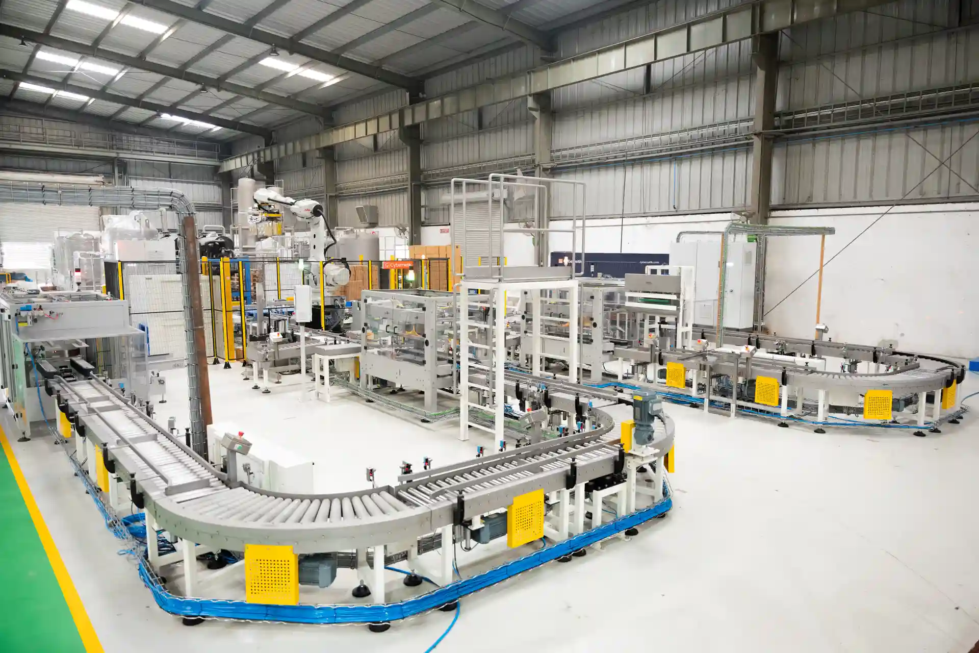
Architecture is usually inherited rather than chosen, because plants grow. A straight line becomes an L when a building is extended, and a spine and spur arrangement emerges when a second production line is added and connected to existing packing. That is normal, but it is worth recognizing when a layout has evolved rather than been designed, because evolved layouts accumulate transfers, and transfers are where problems live.
The Reliability Math Nobody Runs
This is the single most useful calculation in conveying system design, and it is rarely done.
Conveyors in series are dependent. If any one stops, material stops reaching the end, so system availability is the product of the individual availabilities rather than the average of them.
| Conveyors in series | Each at 99% available | Each at 98% available | Each at 95% available |
|---|---|---|---|
| 3 | 97.0% | 94.1% | 85.7% |
| 5 | 95.1% | 90.4% | 77.4% |
| 10 | 90.4% | 81.7% | 59.9% |
Read the bottom row. Ten conveyors, each individually available ninety-five percent of the time, give a system that runs about sixty percent of the time. Every one of those conveyors would be considered acceptable in isolation. Together they produce a line that stops constantly, and each stoppage is attributed to whichever machine happened to fail.
Two conclusions follow. First, individual conveyor reliability matters much more in a long chain than in a short one, and specifying to a lower standard because a conveyor is simple is a false economy at scale. Second, and more usefully, reducing the number of conveyors in series is itself a reliability improvement. Every transfer eliminated removes a link from the chain.
This is the strongest argument for choosing conveying technology that spans a route in one machine. A flexible screw conveyor that bends around an obstacle, or a Z-profile belt that combines horizontal infeed, incline and horizontal discharge, replaces three machines and two transfers with one.
Buffering and Decoupling
The other response to series dependency is to break it, which is what buffering does.
A buffer between two stages allows the upstream stage to continue while the downstream stage is stopped, up to the capacity of the buffer. It converts a hard dependency into a soft one, and it is the difference between a short stoppage costing a minute and costing an hour of ramp-down and restart across the whole plant.
Sizing follows from measurement rather than assumption. The buffer must cover the realistic stoppage duration of the stage it protects, multiplied by the rate at which product arrives. A stage that stops for three minutes while receiving sixty units a minute needs somewhere to put around a hundred and eighty units, and a buffer sized for a thirty-second stoppage will not help.
The measurement to take is not average downtime but the distribution of stoppage durations. Most stoppages are short and a modest buffer covers them; a small number are long and no practical buffer covers those. Sizing for the ninetieth percentile of stoppage duration usually gives a sensible answer, and sizing for the worst case gives an accumulation conveyor longer than the building.
Balancing Throughput Across the System
A conveying network runs at the rate of its slowest element, and identifying which element that is turns out to be harder than it sounds. The obvious candidate is the slowest conveyor, and it frequently is not. Merge points constrain flow because two streams must interleave into one. Divert points constrain it because product must be gapped for the diverter to act. Transfer points constrain it because product needs correct spacing to cross a gap. And any point where product changes orientation adds a rate ceiling that is not written on any machine.
The practical approach is to time each stage across a full shift and find where product waits. Product accumulating in front of a stage means that stage is the constraint; product arriving at a stage that is idle means the constraint is upstream. Automating or speeding a stage that is not the constraint moves the bottleneck without raising output, which is one of the more expensive mistakes in plant improvement.
Control Architecture
At system level, control is what makes a network behave as one machine rather than as a row of independent ones.
Where a network has been assembled over years from separately procured conveyors, the control layer is usually the weakest part of it, because each machine arrived with its own starter and nothing was designed to coordinate them.
 “A reliable conveyor system does more than move material; it connects production stages, absorbs variation, balances throughput, and keeps the entire line running as one coordinated system.”
See it in action
Designing for Change
Plants change more often than conveying systems are replaced, so the useful question at design stage is what will need to change and how expensive that will be.
Three provisions cost little at the outset and a great deal later. Spare capacity in the control system, so an added conveyor does not require a new panel. Physical space at likely expansion points, particularly around merge and divert locations. And a layout that allows a section to be isolated for maintenance without stopping everything, which on a straight-line architecture is frequently impossible.
Benefits at System Level
Applications
Conveying Systems from Cybernetik
Cybernetik designs conveying as part of complete process lines, which means the network is specified alongside the equipment it connects rather than assembled from separately procured machines. The comparison across individual conveyor types is covered in the guide to conveyor belt machines.
| Cybernetik conveying range | Specification |
|---|---|
| Flat belt conveyor | Horizontal and gentle incline duty, slider bed or roller supported |
| Trough belt conveyor | 1,500 to 3,000 kg/hr, upward conveying to 30 degrees, hygienic cGMP construction |
| Flight cleated belt conveyor | Raises product up to 6 m, polyurethane extruded belt, cGMP built |
| Screw conveyor | Up to 40 m length and 10 tons per hour, with multiple inlets and outlets |
| Bucket elevator | C-type and Z-type for vertical lift in a compact footprint |
| Vibratory conveyor | Gentle handling with optional screening or cooling in transit |
| Cooling conveyors | Convective and submerged configurations for in-transit cooling |
| Discharge control | Rotary, CT and combination valves from 1,000 to 6,000 kg/hr with VFD control |
| Line control | Unified PLC and SCADA architecture with recipes propagating across stages |
| Delivery model | Design, build, installation, commissioning and support from one engineering team |
The breadth of that range matters at system level for the reason set out earlier. Reducing the number of conveyors in series is a reliability improvement, so a supplier able to span a route with a screw conveyor, a cleated belt or a bucket elevator, rather than chaining three belt conveyors and two transfers, is removing links from the chain rather than adding them.
Cybernetik has operated for more than three decades, is headquartered in Pune with additional facilities in Gujarat and Raigad and international offices in the United States and UAE, and has installed over 6,000 systems across 30 plus countries, including more than 400 custom automation solutions. With over 600 employees and divisions spanning Process Automation, Packaging Automation, CleanTech, Extraction, Labs and Defence, conveying is designed as part of a production system. Further background is on the Cybernetik about page.