
Key takeaways
Vertical axis wind turbines have spent most of the last century as the road not taken. Georges Darrieus patented the lift driven vertical rotor in 1931. Sandia National Laboratories ran a serious research program on it through the 1970s and 1980s. Then the industry standardised on the three bladed horizontal machine, the supply chain consolidated around that choice, and vertical designs drifted into small scale rooftop products with a reputation for overpromising.
That reputation is being reconsidered, and not by hobbyists. The renewed interest comes from floating offshore wind, where the economics that made horizontal turbines the obvious answer on land stop applying. This article covers how vertical axis turbines work, what they genuinely do better, where they still fall short, and which of the current trends are backed by real engineering programs rather than press releases.
How a Vertical Axis Turbine Works
The defining feature is the axis of rotation. A vertical axis turbine spins around an upright shaft, perpendicular to the ground, which means it accepts wind from any direction without needing to turn to face it. Three configurations account for nearly all designs.
The mechanical consequence of the vertical layout matters more than the aerodynamics. Because the rotor drives a vertical shaft, the gearbox and generator can sit at the base of the structure rather than in a nacelle at hub height. The heaviest components come down to where a technician can reach them with a toolbox instead of a crane.
Vertical Axis and Horizontal Axis Compared
The two architectures trade off against each other rather than one being outright better. The comparison below covers the characteristics that decide which suits a given site.
| Characteristic | Vertical axis (VAWT) | Horizontal axis (HAWT) |
|---|---|---|
| Wind direction | Omnidirectional, no yaw system needed | Must be yawed into the wind continuously |
| Generator position | At or near ground level | In the nacelle at hub height |
| Maintenance access | Ground level for most drivetrain work | Requires climbing or crane access |
| Aerodynamic efficiency | Lower, roughly 30 to 40 percent for lift driven designs | Higher, typically 45 to 50 percent |
| Fatigue loading | Cyclic load reversal every rotation | Steadier loading in uniform flow |
| Behaviour in turbulence | Handles gusty, shifting wind well | Loses output in turbulent flow |
| Noise | Lower tip speeds, quieter | Higher tip speeds, more audible |
| Commercial maturity | Early stage, mostly small scale and prototypes | Mature global supply chain at multi megawatt scale |
What Vertical Axis Turbines Do Well
Where They Still Fall Short
Any honest assessment has to deal with why the industry went the other way, because those reasons have not disappeared.
Aerodynamic efficiency is the first. A vertical blade changes its angle of attack continuously through every rotation, spending part of each revolution producing little useful force and part of it stalled. Lift driven vertical designs typically convert 30 to 40 percent of available wind energy against 45 to 50 percent for a modern horizontal turbine, against a theoretical Betz limit of 59.3 percent.
Fatigue is the second and more serious. That same rotational cycle reverses the load on each blade twice per revolution, so the structure accumulates fatigue damage far faster than a horizontal blade in steady flow. The Sandia programs of the 1980s ended largely because blade root fatigue proved harder to engineer around than expected with the tools available then.
The third is not technical. Horizontal turbines carry four decades of manufacturing scale, certification precedent, aeroelastic modelling tools and trained supply chain. Recent reviews identify the absence of a comparable industrial ecosystem as the primary obstacle to vertical designs competing, ahead of any single engineering limitation.
Where Vertical Axis Turbines Are Used Today
 “The future of vertical axis wind energy may depend less on improving the rotor alone and more on solving the structural, manufacturing, and floating-platform challenges that determine whether the technology can scale.”

See it in action
Future Trends Worth Following
Floating offshore is the real opportunity
On land, the turbine itself accounts for roughly 65 percent of total system cost, so efficiency dominates the economics and the horizontal machine wins. In deep water the ratio inverts. The turbine falls to around a quarter of system cost and the floating platform becomes the largest single expense. Sandia National Laboratories has shown that a vertical axis design, with its low centre of gravity and ground level drivetrain, allows a substantially lighter and cheaper platform, and that this platform saving can reduce levelised cost of energy even though the rotor converts less wind energy.
That is the argument in one sentence: offshore, a less efficient turbine on a much cheaper foundation can beat a more efficient turbine on an expensive one.
Demonstrators are in the water
The field has moved past concept papers. A consortium of Japanese energy and heavy industry companies installed an experimental floating vertical axis turbine off Iki City in Nagasaki Prefecture, with a three straight bladed rotor on a cylindrical floating foundation, and began a year long demonstration in July 2026. In Europe, Swedish developer SeaTwirl has drawn European Commission funding for an H-type Darrieus rotor on a spar floater. In the United States, ARPA-E has funded floating vertical axis concepts through its ATLANTIS program.
Scale targets are rising
Sandia’s current offshore rotor work targets machines in the 10 to 20 MW class with a goal of cutting cost of energy by more than 20 percent against fixed bottom horizontal systems. Whether those targets are met is open, and serious reviews published this year still frame vertical axis offshore wind as unproven rather than imminent.
Manufacturing is the gating factor
Almost every roadmap for large vertical axis turbines converges on the same conclusion. The blades are long, structurally demanding composite parts that need to be produced repeatably and joined precisely, and the industry lacks the manufacturing base to do that at volume. Rotor material and manufacturing strategy is now an explicit research thrust rather than an afterthought, which is a meaningful signal about where the bottleneck sits.
The Manufacturing Question Behind the Technology
Whatever rotor architecture eventually wins offshore, the constraint is the same one that has governed wind energy for twenty years: large composite structures have to be machined and joined to tolerances measured in fractions of a millimetre, on parts tens of metres long. That is a production engineering problem, not an aerodynamics problem, and it is the part of wind manufacturing where automation determines whether a design scales.
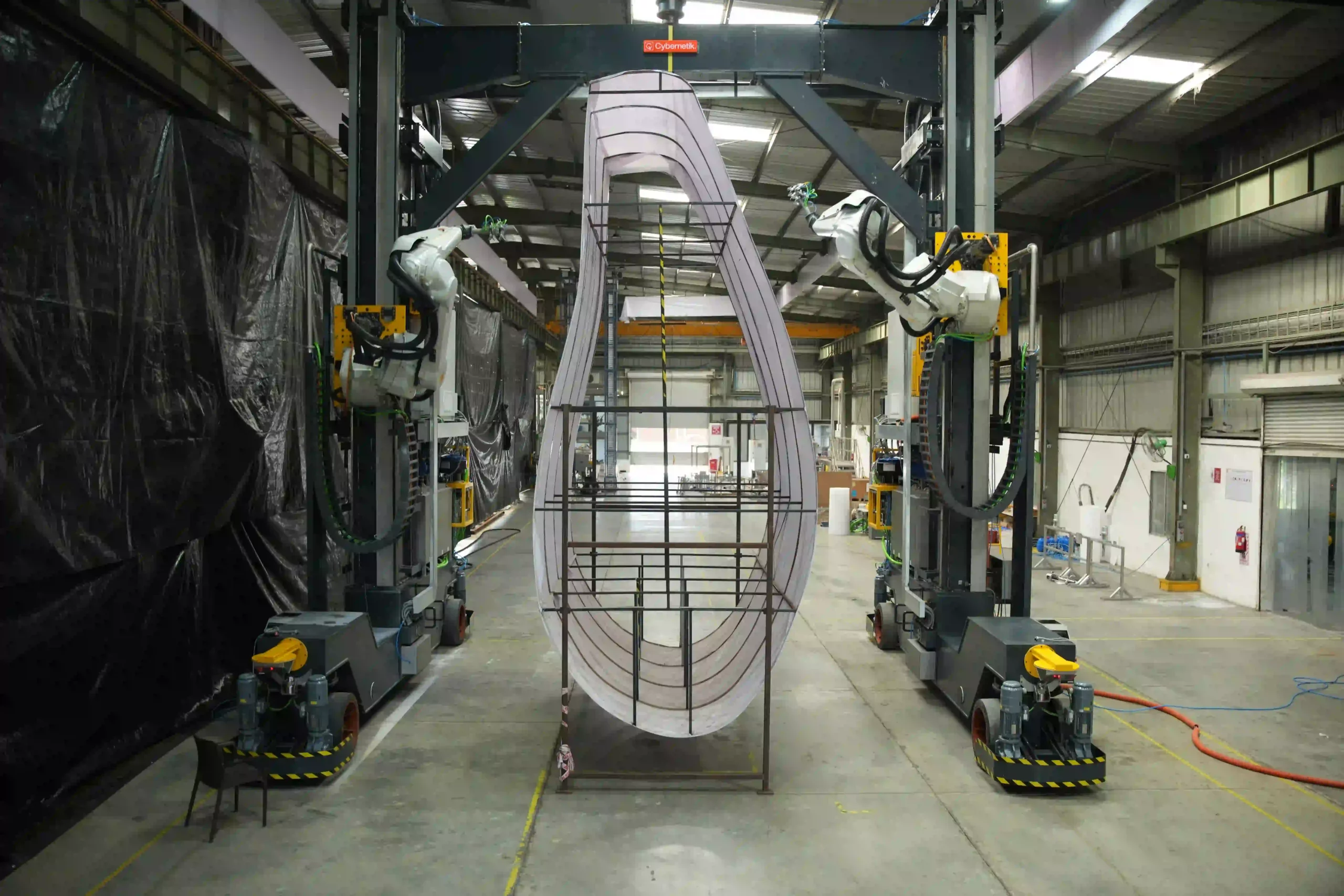
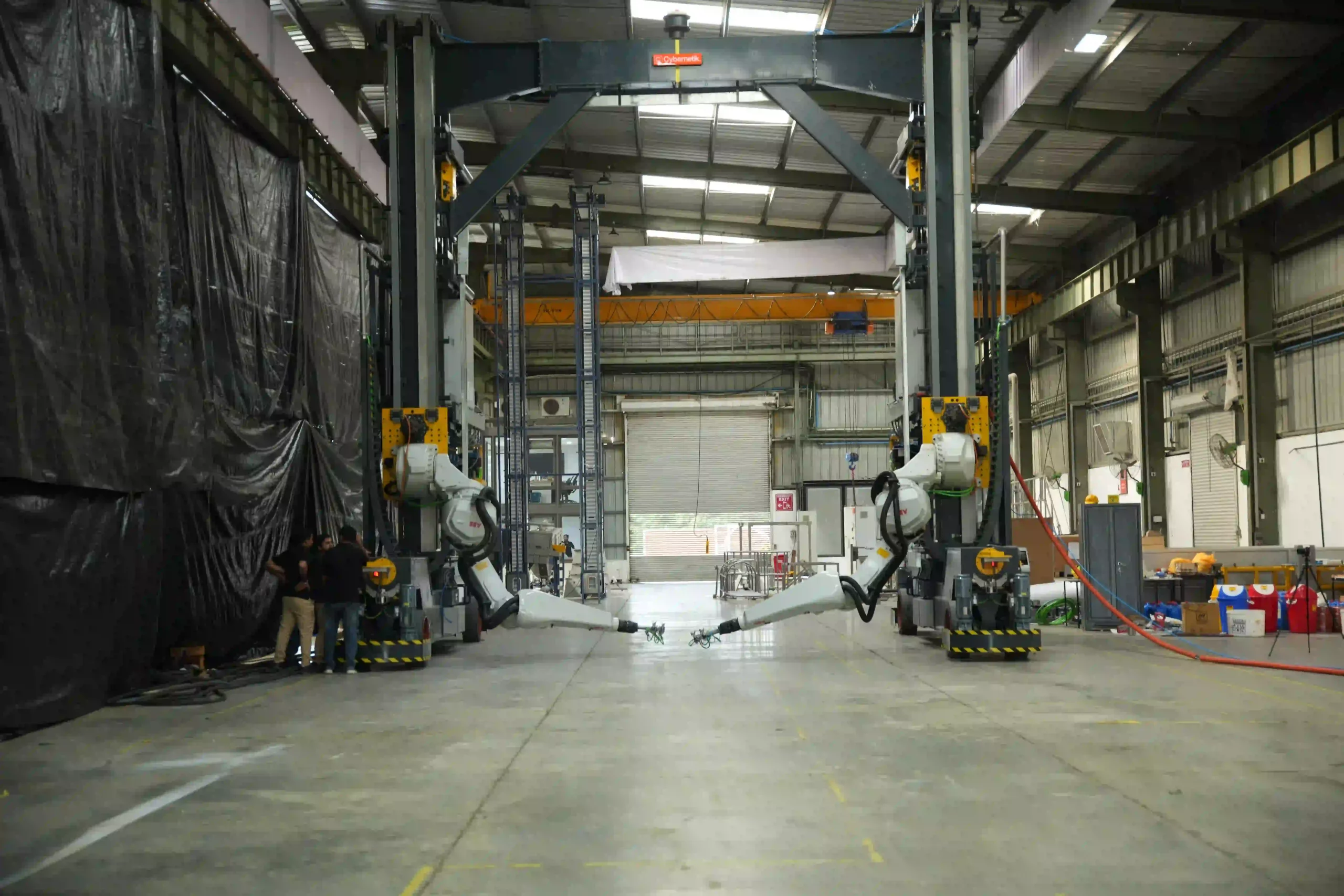
Cybernetik built the first robotic machining automation system of its kind for sawing, milling and drilling at the root end of wind turbine blades, holding pitch circle diameter to within a millimetre on rotors up to 4,800 mm across and blades up to 100 metres long. The blade root machining process covers why that joint is the hardest part of any blade to manufacture, vertical or horizontal.
The company has operated for more than three decades, is headquartered in Pune with offices in the United States and the UAE, and has installed over 6,000 systems across 30 plus countries, including more than 400 custom robotic automation solutions. In wind energy that work has been delivered for manufacturers including Siemens Gamesa and Suzlon.