
Key takeaways
An electric vehicle battery pack is assembled under constraints that no other battery product carries. It has to fit a space defined by the vehicle rather than by the pack, survive a crash without releasing energy, keep several hundred cells within a few degrees of each other for a decade, and remain sealed against road spray and salt for the life of the car.
None of those requirements is negotiable, and several of them work against each other. Reducing mass argues for structural integration; serviceability argues against it. Packing more energy into the floor argues for eliminating gaps between cells; thermal runaway containment argues for keeping them apart. Every EV pack in production is a settled position on those trade-offs, and the assembly line is built to execute that particular settlement rather than a generic one.
The underlying stages, cell testing, welding, module build, sealing and end of line verification, are common to lithium pack production generally and are covered in the guide to lithium battery pack assembly. This article covers what changes when the pack goes into a vehicle, and why those changes drive so much of the equipment specification.
The Constraints an EV Pack Is Built Under
Four requirements shape every decision on an EV pack line, and they frequently pull against each other.
These constraints reach further into the line than they first appear. A fixed envelope means tooling has to approach from directions that suit the vehicle rather than the assembler, so robots work in confined spaces and fastening access is frequently awkward. Structural duty means torque values matter as engineering data rather than as assembly convenience, and they have to be recorded. Thermal requirements mean interface materials are dispensed to a specification rather than applied, and mass targets mean housings are thinner and less forgiving of handling than they would otherwise be.
The result is that an EV pack line looks different from a stationary storage line built from the same equipment. The stations are recognizably similar; the tolerances, the verification density and the record-keeping are not.
Module to Pack, or Cell to Pack
Traditional architecture builds cells into modules and modules into a pack. The module is a testable sub-assembly, it can be replaced in service, and it provides an intermediate structure that simplifies handling. Cell to pack designs remove that intermediate level, mounting cells directly into the pack structure. Mass falls, volumetric efficiency rises and part count drops. What also disappears is the ability to test a sub-assembly before it is structurally committed, and the ability to replace one module in the field.
For the assembly line the consequence is significant. Without a module stage, every quality check has to happen before cells are bonded into the pack, because after that point a marginal cell cannot be removed. The precision bar on cell grading, insulation placement and weld verification rises accordingly, and so does the cost of a defect found late.
There is a commercial dimension too. A module-based pack that fails in service can often be repaired by replacing one module, which keeps warranty cost proportionate to the fault. A structurally integrated pack with the same fault may be uneconomic to repair, so the manufacturer carries the whole pack cost rather than a fraction of it. That shifts the value of first-pass quality upward substantially, and it is one reason cell-to-pack manufacturers invest more heavily in inline verification than the architecture alone would suggest.
Most manufacturers currently run both approaches across different platforms, which means an assembly line that can accommodate more than one module configuration has real value rather than theoretical flexibility.
The Assembly Sequence
A production EV battery pack assembly line is typically arranged in three zones, and the division reflects how the product changes character as it progresses.
Zone 1: cell to module
Cells are fed and unloaded from incoming trays, barcodes are read into the traceability record, and terminals are plasma cleaned. Open circuit voltage and internal resistance are measured on every cell and cells are sorted into bands. Robotic pick and place then loads them into holders, with insulation paper applied and its presence verified by detection rather than assumed. Busbars are placed at top and bottom cell holders, polarity is checked, and welds are made and verified for integrity on both module faces. Sense wiring and main positive and negative connections are soldered and routed before the module is unloaded.
This zone determines most of what the finished pack will be. Sorting decides how uniformly it ages, plasma cleaning decides how consistently it welds, insulation placement decides whether it develops a latent short, and weld verification decides whether thousands of joints are actually sound. Everything downstream assembles what this zone produced; it cannot improve it.
Zone 2: pack assembly
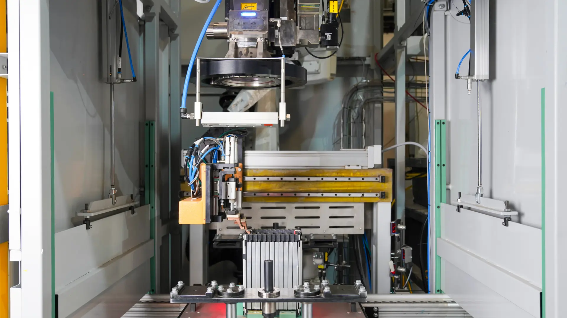
Modules are flipped and inserted into the pack housing with thermal pads and Nomex sheets applied between them. Temperature sensing is installed, telematics gaskets are assembled, and the battery management system is mounted and connected. Bottom plate gaskets and the BMS mounting plate are fitted, and the top cover is closed and cleaned.
The character of the work changes here. Zone 1 handles small components at high repetition; Zone 2 handles a large, heavy, increasingly valuable assembly at low repetition, where a single handling error writes off everything already built into it. It is also the zone where the pack becomes electrically live as modules are connected, so the sequence has to keep operators out of the current path by design rather than by procedure.
Zone 3: end of line testing
The BMS is programmed and the telematics control unit mounted and tested. The pack undergoes air leakage testing to confirm the seal, end of line electrical testing to confirm function, and laser marking to fix its identity before dispatch.
End of line testing confirms the pack works. It does not confirm the pack was built correctly, and the distinction matters. A pack with a marginal weld, a slightly misplaced thermal barrier or a cell that sorted into the wrong band will pass every end of line test and fail in the field years later. That is why verification belongs at the stations that create those characteristics, with end of line acting as a final gate rather than as the quality system.
The Challenges
| Challenge | Why it is specific to EV packs | How the line addresses it |
|---|---|---|
| Fixed packaging envelope | The pack shape is dictated by the vehicle floor, not by what is convenient to build | Assembly designed around a geometry that cannot be changed, with tooling reaching into confined spaces |
| Crash load paths | The pack is a structural member and must protect cells under intrusion | Controlled torque sequencing on structural fasteners, with values recorded per pack |
| Thermal runaway propagation | A single cell failure must not cascade through the pack | Barrier and thermal pad placement verified rather than assumed, since a missing sheet is invisible once closed |
| Temperature uniformity | Cells at different temperatures age at different rates across a decade of service | Thermal interface material dispensed to controlled bead weight and path across the cooling interface |
| High voltage during build | Modules become live long before the pack is finished | Insulation verified at multiple stages, and operators kept out of the current path by design |
| Sealing to an ingress rating | The pack sits under a vehicle exposed to water, salt and debris | Gasket seating under controlled fastening, verified by air leak testing on every unit |
| Mass | Every kilogram costs range | Structural integration that removes duplicated housings, at the cost of serviceability |
The thermal runaway row deserves particular attention because it is the one with the least forgiving failure mode. Barriers, thermal pads and Nomex sheets exist to stop a single cell failure cascading through the pack. Once the top cover closes, a missing or misplaced sheet is invisible and remains so until the pack is in a vehicle. This is why placement is verified at the station rather than checked by sampling.
Best Practices
 “As battery packs become more structurally integrated, first-pass quality becomes increasingly important because defects discovered late can carry the cost of the entire pack”

See it in action
Scaling from Prototype to Volume
EV programs move faster than most manufacturing projects, and the assembly line usually has to serve two very different phases. early production is low volume and high variability. Designs change, cell suppliers change, and the priority is proving the pack rather than producing it economically. Manual and semi-automatic assembly suits this phase, because changes are cheap to accommodate and capital commitment stays low.
Volume production inverts every one of those priorities. Takt time governs, variability is the enemy, and traceability becomes a warranty and regulatory requirement rather than a useful record. Manual processes that were adequate at pilot volumes become the constraint, and the quality characteristics that mattered least at low volume, consistency across thousands of units, matter most.
The practical difficulty is that these phases overlap. A manufacturer is frequently ramping one platform while piloting the next, so the line has to run production reliably and accommodate change at the same time. Two decisions make that manageable. Specify the traceability layer from the beginning, because retrofitting data capture into a running line is expensive and rarely complete. And build in format flexibility, so a cell change or a second module configuration is a recipe and tooling question rather than a new line.
EV Pack Assembly from Cybernetik
Cybernetik builds turnkey EV battery pack assembly lines covering all three zones, from cell feeding through module build and pack assembly to end of line testing, as one integrated system. The wider battery pack assembly automation range also covers stationary storage, where the same equipment is configured for different priorities.
| Cybernetik EV pack assembly capability | Specification |
|---|---|
| Cell formats handled | Cylindrical 18650, 21700 and 32140, plus prismatic, pouch and blade |
| Cell diameters | 32, 33, 35, 40, 42 and 46 mm |
| Line speed | Up to 6,000 cells per hour |
| Zone 1, cell to module | Feeding, barcode reading, plasma cleaning, OCV and IR testing, sorting, robotic pick and place, insulation paper application and detection, busbar placement, polarity checking, weld integrity testing on both module faces |
| Zone 2, pack assembly pallet line | Module flip over, thermal pad and Nomex sheet application, temperature sensing, telematics gasket assembly, BMS mounting and connection, bottom plate gasket, top cover closing and cleaning |
| Zone 3, end of line testing | BMS programming, TCU mounting and testing, air leakage testing, EOL electrical testing, laser marking |
| Welding | Laser and resistance welding with inline weld integrity verification |
| Robotics base | More than 400 custom robotic automation solutions delivered |
| Delivery model | Full accountability for end-to-end project delivery |
Cybernetik has operated for more than three decades, is headquartered in Pune with additional facilities in Gujarat and Raigad and international offices in the United States and UAE, and has installed over 6,000 systems across 30 plus countries, including more than 400 custom robotic automation solutions. In electric mobility that work has been delivered for manufacturers including Hero MotoCorp, TVS Motor, Livguard and Matter. Further background sits on the Cybernetik about page.