
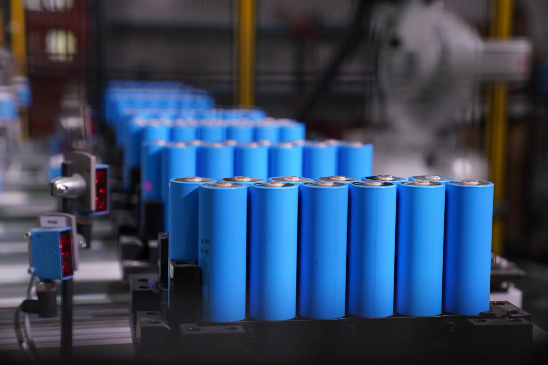
Key takeaways
Battery cell manufacturing is one of the most capital-intensive forms of production in modern industry, and one of the least intuitive. It combines a continuous web coating process that resembles printing, a discrete assembly process that must run in air drier than any desert, and a testing stage that ties up weeks of production before a single cell can be sold.
Those three phases have almost nothing in common operationally, which is why cell plants are organized into distinct areas with different equipment, different environmental requirements and different people running them.
This article covers each area, the equipment in it, and where automation and inline measurement actually change the outcome. For the wider chain including module and pack build, see the battery manufacturing process guide.
The Three Areas of a Cell Plant
| Plant area | What happens there | Dominant characteristic |
|---|---|---|
| Electrode manufacturing | Slurry mixing, coating, drying, calendering, slitting and vacuum drying | A continuous web process, closer to printing or paper converting than to assembly |
| Cell assembly | Notching, winding or stacking, tab welding, enclosure, electrolyte filling and sealing | Discrete high-speed assembly in a controlled dry environment |
| Formation and aging | First charge and discharge cycles, degassing, aging, grading and final testing | Long duration, capital and space intensive, with large amounts of work in progress |
The division matters commercially as well as operationally. Electrode manufacturing sets cell capacity and is where most quality is determined. Cell assembly sets throughput and is where most safety defects originate. Formation and aging consume floor space, capital and time out of all proportion to what they visibly do, and they are where a plant discovers what it actually made.
Electrode Manufacturing
Mixing
Active material, conductive additive and binder are combined into a slurry in planetary or twin-screw mixers, frequently under vacuum to exclude entrained air. Cathode slurries typically use a fluoropolymer binder in solvent; anode slurries commonly use water-based systems. The controlled variables are solids content, viscosity and dispersion quality, and dispersion is the one that cannot be corrected afterward. Agglomerates that survive mixing travel through every subsequent stage intact.
Coating and drying
Slurry is applied to metal foil, aluminum for the cathode and copper for the anode, usually by slot-die coating on both faces. Coating weight per unit area is the single most controlled parameter in the plant because it sets cell capacity directly, and it is measured continuously in-line by beta or X-ray gauges scanning across the web.
The coated web then passes through multi-zone drying ovens that can run tens of meters long. Drying profile matters as much as drying capacity: too aggressive and binder migrates toward the surface, weakening adhesion to the foil. For solvent-based cathode coating, the vapor is captured and the solvent recovered by condensation and distillation, which is a significant part of both the capital cost and the operating complexity of a cell plant.
Calendering
The coated foil is compressed between hardened rolls to a target thickness and porosity. This densifies the electrode, improves particle-to-particle contact and raises energy density. Line load is controlled by servo or hydraulic systems and thickness is gauged continuously. Over-compression fractures active material particles and closes the pathways electrolyte needs, so the process window is narrower than it appears.
Slitting and vacuum drying
The wide web is slit into electrode-width strips by rotary shear slitters. Edge quality here is a safety characteristic rather than a cosmetic one, since burrs left by worn blades can pierce the separator later and cause an internal short. Slit electrodes are then vacuum dried to remove residual moisture before they enter the assembly area.
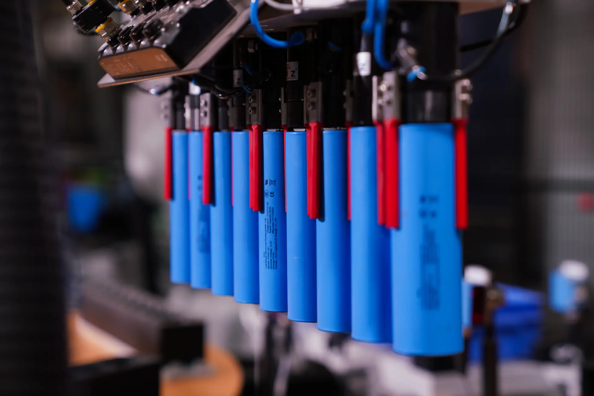
Cell Assembly
Notching and electrode preparation
Tabs are formed by die cutting or laser notching. Laser notching avoids tool wear and the particulate that mechanical cutting generates, at the cost of higher capital and a need to control the debris the laser itself creates.
Winding or stacking
Cylindrical and many prismatic cells are wound into a jelly roll on high-speed winders. Pouch and some prismatic formats are built by stacking, either Z-folding a continuous separator between electrode sheets or placing single sheets in sequence. Stacking generally gives better energy density and thermal behavior; winding is faster and mechanically simpler.
Either way, alignment tolerance is tight. Anode must overhang cathode at every edge, and where it does not, lithium plates at the exposed boundary during charging. This is one of the characteristics that inline X-ray inspection exists to verify, since it is invisible once the cell is enclosed.
Enclosure, filling and sealing
Tabs are joined by ultrasonic or laser welding, and the assembly is enclosed, in a drawn can for cylindrical and prismatic formats or in deep-drawn aluminum laminate for pouch cells. The cell is vacuum dried again, filled with electrolyte under vacuum, allowed to wet through the electrode stack, and sealed by laser welding or heat sealing.
Electrolyte dosing accuracy matters in both directions. Too little and part of the electrode never participates; too much adds cost and mass and can cause pressure problems later. Wetting time is also a genuine process step rather than a delay, since electrolyte has to penetrate a tightly compressed stack.
Formation and Aging
The finished cell is electrically inert until it is formed. Formation applies the first controlled charge and discharge cycles, during which a solid electrolyte interphase layer develops on the anode surface. The quality of that layer largely determines how the cell will age for the rest of its life, which makes formation protocol one of the most closely guarded parameters in cell manufacturing.
Formation equipment consists of cyclers with very large channel counts, since every cell must be individually connected and cycled. Modern systems recover energy between channels rather than dissipating it, which materially reduces the electricity consumed. Pouch cells are degassed after formation to remove gas generated during the process, then resealed.
Cells then age under controlled temperature for days to weeks while self-discharge behavior is monitored. This is what identifies cells with microscopic internal shorts, which read as normal on every instantaneous measurement and reveal themselves only through voltage decay over time. Finally cells are graded by capacity, open circuit voltage, internal resistance and self-discharge rate, and sorted.
Formation and aging are where a cell plant ties up the most working capital. Weeks of production sit in temperature-controlled racks representing material and processing cost already spent, and compressing that time to release capital is a decision with direct quality consequences.
The Infrastructure Around the Process
Two environmental requirements drive much of a cell plant capital cost and most of its energy bill.
Dry rooms maintain dew points far below anything conventional air conditioning produces, because moisture at parts per million reacts with the electrolyte salt to form hydrofluoric acid and degrade the cell. Dry room air handling is typically the largest single utility load in a cell plant, and its capacity constrains where and how fast the plant can expand.
Particle control matters equally. A metallic particle of a few tens of micrometers landing on an electrode can bridge the separator and short the cell, so cleanliness standards apply through electrode handling and assembly. Combined with solvent recovery, formation capacity and weeks of aging inventory, this is why cell plants are built at gigawatt-hour scale: nothing smaller absorbs the overhead.
Automation and Inline Control
Where Yield Is Lost
New cell plants routinely start well below target yield and take several quarters to reach it. The reason is structural rather than a reflection of competence.
Almost every defect in cell manufacturing is created early and detected late. Dispersion problems in mixing, coating weight variation, particle cracking in calendering and burrs in slitting all pass visual inspection and reveal themselves at formation, at grading, or in the field. By the time a defect is detected, the plant has added weeks of processing and formation time to a cell that will be scrapped.
That latency is what makes inline measurement economically decisive rather than merely good practice. Catching a coating weight excursion at the coater costs a few meters of web. Catching the same excursion at grading costs everything that was done to those electrodes in between, including formation channel time that could have been used for good cells.
 “Battery cell quality is determined long before final testing, making precise coating, calendering, slitting, assembly, and formation critical to reliable cell performance.“

See it in action
What Is Changing
Three developments are altering cell manufacturing economics, and all three affect the equipment rather than the chemistry.
Dry electrode coating removes the solvent, and with it the drying ovens and solvent recovery that dominate electrode area footprint and energy consumption. Where it can be made to work at production quality, it removes a large part of the plant.
Larger cell formats reduce the number of cells per pack, which shifts effort from cell assembly speed toward per-cell quality, since each unit now represents more of the finished product.
And cell-to-pack architectures place greater demands on dimensional consistency, because cells are bonded directly into structure with no module to absorb variation.
Where Cybernetik Fits
Cybernetik builds pack assembly automation rather than cell manufacturing equipment. Cell plants are a separate capital category requiring dry rooms, solvent recovery and formation capacity at gigawatt-hour scale. What Cybernetik supplies is what happens to those cells afterward: battery pack assembly automation from cell verification through module build to end of line testing.
The connection between the two is closer than it appears. Cell grading at the end of cell manufacturing and cell sorting at the start of pack assembly are doing the same job from opposite ends, and a pack ages at the rate of its weakest cell regardless of how well the cells were made.
| Cybernetik battery pack assembly capability | Specification |
|---|---|
| Cell formats handled | Cylindrical 18650, 21700 and 32140, plus prismatic, pouch and blade |
| Cell diameters | 32, 33, 35, 40, 42 and 46 mm |
| Line speed | Up to 6,000 cells per hour |
| Incoming cell verification | OCV, IR and ACIR testing on every cell with robotic sorting onto parallel conveyors |
| Surface preparation | Plasma cleaning with vision-confirmed insulation application and polarity checking |
| Joining | Laser and resistance welding with inline weld integrity testing on every joint |
| Pack assembly | Thermal pad and barrier placement, BMS mounting, gasket and cover assembly |
| End of line | BMS and TCU programming, air leakage testing, electrical testing and laser marking |
| Traceability | Barcode and RFID capture with MES connectivity and process logging |
| Robotics base | More than 400 custom robotic automation solutions delivered |
Cybernetik has operated for more than three decades, is headquartered in Pune with additional facilities in Gujarat and Raigad and international offices in the United States and UAE, and has installed over 6,000 systems across 30 plus countries. In battery manufacturing that work has been delivered for manufacturers including Hero MotoCorp, TVS Motor, Livguard and Matter. Further background sits on the Cybernetik about page.