
Key takeaways
Almost every wind turbine generating power into a grid today is an axial flow machine. Wind travels along the axis of rotation, passes through a rotor mounted perpendicular to it, and leaves slower than it arrived. The energy captured is the difference. That description covers the three bladed machines on every ridgeline and every offshore array in operation.
The word axial carries more than one meaning in wind engineering, and the distinctions matter when reading specifications. This article sorts them out, then works through how an axial flow rotor actually extracts energy, how the machine around it is designed, which drivetrain configurations are in use, and where each finds application.
Three Meanings of Axial in Wind Engineering
All three are covered below. The alternative architecture, in which the rotor spins around an upright shaft and accepts wind from any direction, is covered separately in the article on vertical axis wind turbines.
The Working Principle: How an Axial Rotor Extracts Energy
The intuitive picture, that blades are pushed by wind, is wrong. Modern rotors work on lift, not drag. Each blade is an aerofoil, and the combination of wind speed and the blade’s own rotational velocity produces a relative airflow that strikes the section at a small angle of attack. That generates lift, most of which acts in the plane of rotation and drives the rotor around. Blades are twisted along their span precisely because rotational velocity increases toward the tip, so the section angle must change to hold an efficient angle of attack from root to tip.
Available power in the wind scales with the cube of wind speed and with the square of rotor diameter. Doubling wind speed makes eight times the power available; doubling rotor diameter makes four times. This is the whole economic logic behind the growth in rotor size, and why offshore machines in current commercial deployment run from roughly 15 to 26 MW with hub heights commonly between 125 and 150 metres.
Axial induction and the Betz limit
A rotor cannot extract all the kinetic energy passing through it. To capture energy it must slow the air, but if it slowed the air to a standstill no further air could pass through and power output would be zero. There is an optimum somewhere between taking nothing and taking everything.
Axial induction factor is the measure of that slowdown, expressed as the fractional reduction in wind speed at the rotor plane compared with the free stream ahead of it. Momentum theory shows the optimum sits at one third, meaning the ideal rotor slows the air by a third as it passes through. At that point the extractable fraction of available power reaches sixteen twenty sevenths, or 59.3 percent. This is the Betz limit, and it is a physical ceiling rather than an engineering target.
Real rotors do not reach it. Tip losses, blade drag, wake rotation and finite blade count take their toll, and a well designed modern rotor achieves a power coefficient somewhere around 0.45 to 0.50. Anyone advertising a turbine above the Betz limit is either measuring something else or selling something.
Tip speed ratio
Tip speed ratio is blade tip velocity divided by wind speed, and it couples rotor design to control strategy. Three bladed lift driven rotors operate most efficiently around a ratio of six to eight. Below that, capture is incomplete; above it, drag and noise climb sharply. Variable speed operation exists to hold this ratio near optimum as wind speed changes.
Design Anatomy of an Axial Flow Turbine
Drivetrain Configurations
How rotor motion becomes electricity is the single largest architectural decision in turbine design, and it is where the third meaning of axial appears.
| Configuration | How it works | Advantages | Trade offs |
|---|---|---|---|
| Geared, high speed | Three stage gearbox steps rotor speed up to around 1,500 rpm for a compact generator | Lightest and cheapest generator, mature supply chain | Gearbox is the highest failure rate component in the drivetrain |
| Hybrid, medium speed | Single or two stage gearbox feeding a mid speed permanent magnet generator | Smaller gearbox, better reliability than high speed | Still contains gearing, heavier generator |
| Direct drive, radial flux | Rotor drives a large diameter permanent magnet generator with no gearbox | No gearbox to fail, high availability offshore | Very large diameter, heavy, high rare earth magnet content |
| Direct drive, axial flux | Disc shaped generator where magnetic flux runs parallel to the shaft axis | High torque density, compact axial length, favourable weight per kW | Manufacturing complexity, thermal management, less field proven at utility scale |
Axial flux generators are the interesting entry on that list. Arranging magnets and windings on parallel discs, with flux running along the shaft axis, produces high torque in a short axial length. That geometry suits direct drive applications where a conventional radial machine would need an impractically large diameter. The obstacle is manufacturing rather than physics: axial flux machines demand tight air gap control across large disc faces, and holding that tolerance repeatably in production is difficult.
 “The future of axial wind turbines depends not only on larger and more efficient rotors, but on manufacturing systems capable of producing increasingly large blades and critical root connections with repeatable precision.”

See it in action
Control Strategy and Configuration Choices
Upwind rotors, with blades ahead of the tower, dominate production because they avoid the tower shadow effect that costs a downwind rotor lift and generates noise each time a blade passes behind the tower. Downwind configurations self align without yaw drives, which keeps them in play for smaller machines and some floating concepts.
For power regulation, pitch control has displaced stall control on utility machines. Stall regulated designs let the blade aerodynamically stall as wind rises, which is simple but crude. Pitch regulation actively rotates the blades to hold rated output between rated wind speed and cut out, typically around 25 metres per second, and feathers them entirely to shut down. It costs more and delivers far better output and load control.
Applications by Scale
The Manufacturing Constraint Behind Rotor Growth
Rotor diameter is the lever that drives turbine economics, and it is limited less by aerodynamics than by manufacturing. A blade over 100 metres long has to be moulded, machined and joined to tolerances measured in fractions of a millimetre at the root, then transported and bolted to a hub in the field. Every increase in blade length raises the precision demanded at the joint that holds it on, which is why root end machining automation has become a gating capability for blade manufacturers rather than a productivity improvement.
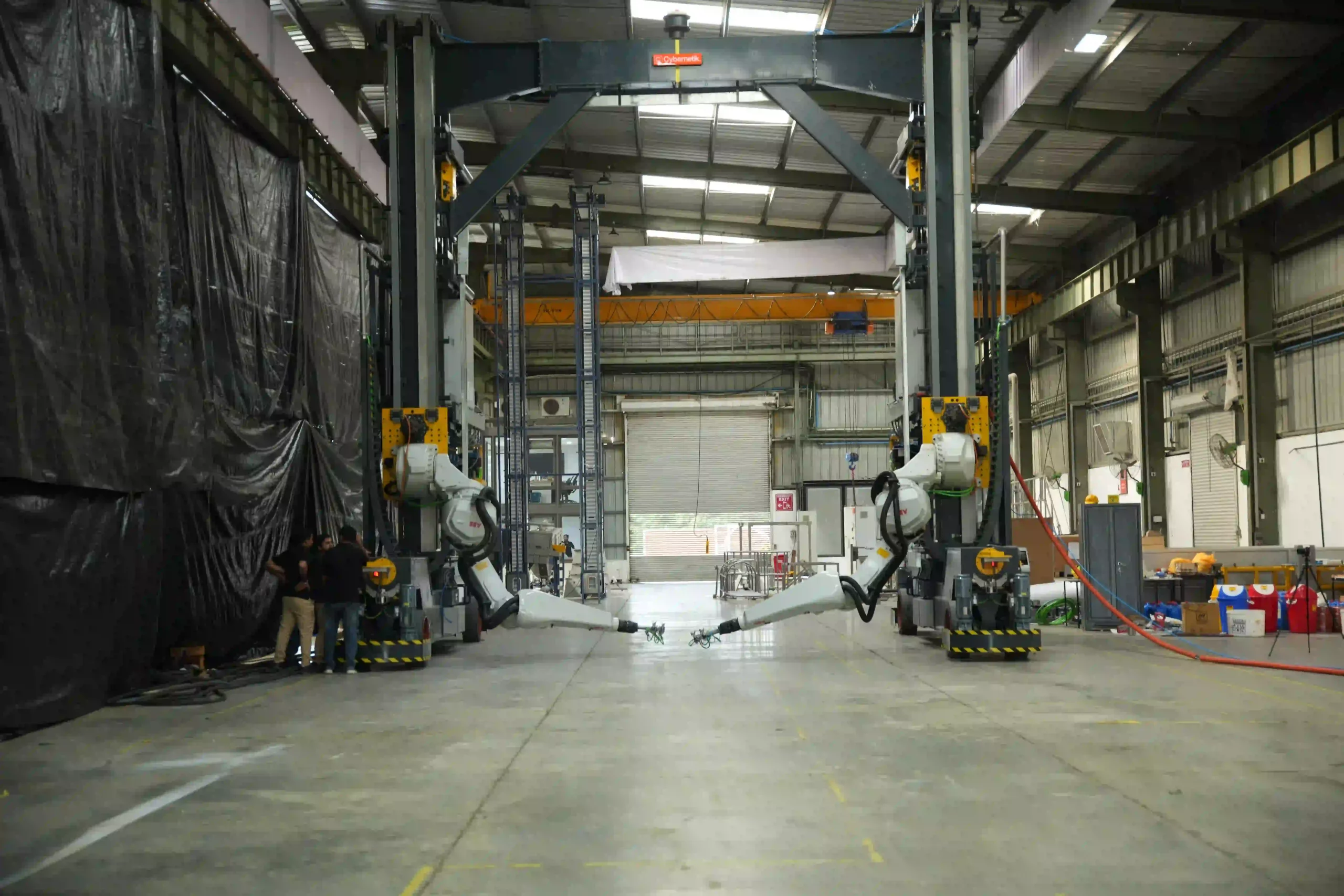
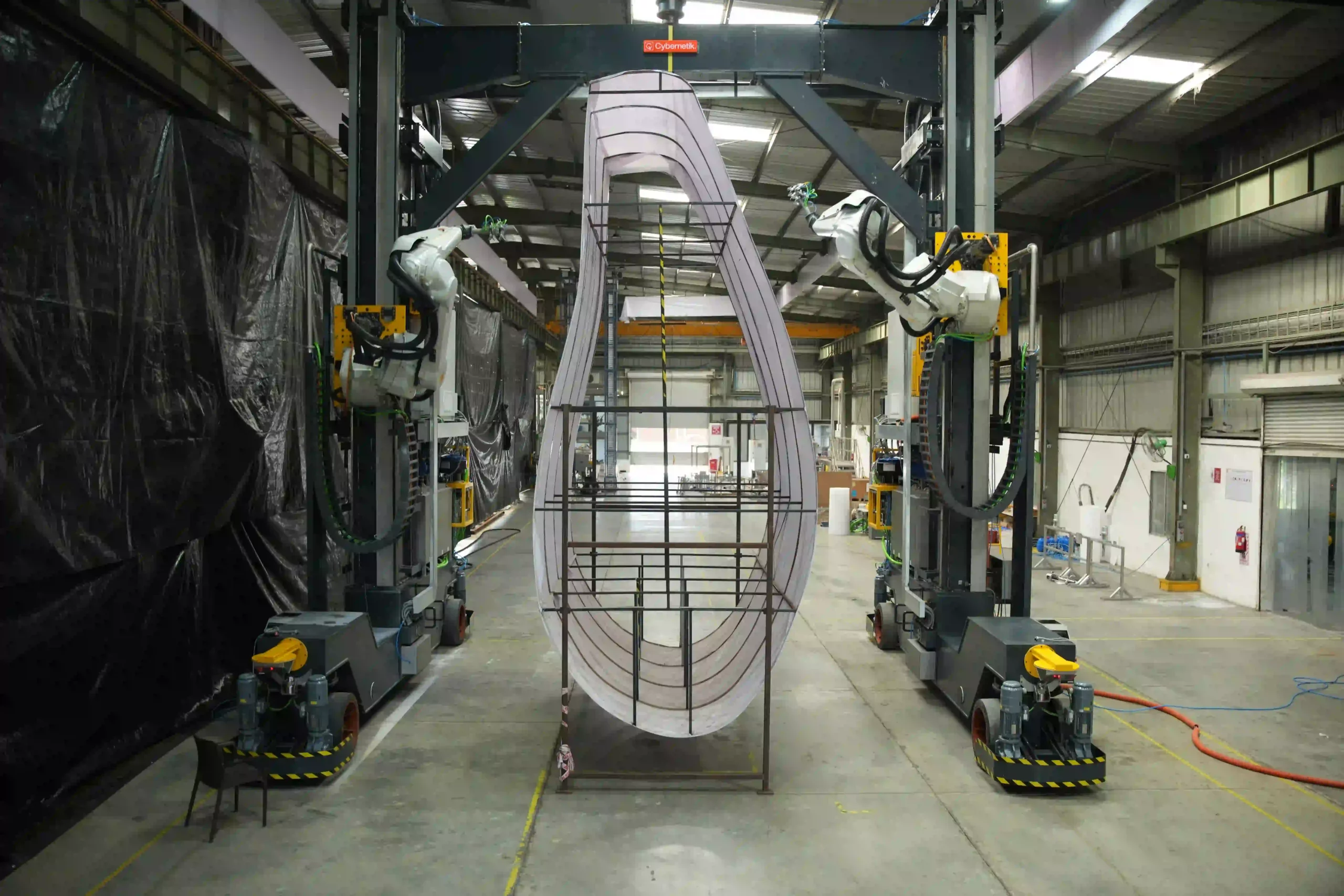
Cybernetik built the first robotic machining system of its kind for sawing, milling and drilling at the blade root, handling pitch circle diameters from 2,800 to 4,800 mm and blades up to 100 metres, holding PCD to within a millimetre and milling flatness to 0.500 mm. The blade root machining guide sets out the full eight stage sequence and the tolerances involved.
The company has operated for more than three decades, is headquartered in Pune with offices in the United States and the UAE, and has installed over 6,000 systems across 30 plus countries, including more than 400 custom robotic automation solutions. In wind energy that work has been delivered for manufacturers including Siemens Gamesa and Suzlon.